Well constant reader- Amazingly I am beginning to run out of tasks on this car and I think its time to be methodical about whats left so that I don't forget anything. There are a number of small jobs I've been leaving, but I'm now ticking them off and this is what I've done so far.
- I tightened up the upper suspension arm-to-chassis bolts now that the car has been standing on its own "feet" for a while; 50 ftlb as specified.
 |
| Upper suspn arm seen from behind front wheel. But and locknut. |
- I replaced the (new) rubber boot on the LHS track-rod end that had split as it was mounted.
- I needed to tighten up the exhaust cam-cover bolts as there was an oil leak on longer running and also the water pump to manifold hose- a short and troublesome length that is awkward to mount and awkward to tighten.
- Clutch pedal action was heavy and had a tremendous drag- I adjusted the actuating push-rod by lengthening it (i.e. screwing it out of the clevis) and this solved the problem.
As far as recommissioning (yes I am really using that word), then the jobs left to do fall into three camps- there are a few that I need to do, a few that I will need to get done (at time of MOT)and a few more that I am hoping will not be needed immediately to get the car on the road.
Jobs left for me (see on):
Bleed the Brakes: I have rebuilt but never commissioned the system. There was a problem bleeding the rear LHS caliper that I need to revisit. Hopefully just a blocked nipple.
Check brake fluid warning light: the light so far has remained "on" in the dash.
Bleed PAS: No idea if this will still be fluid-tight.
Cooling system: Bleed heater and check otter switch.
Body: Refit the bonnet with a new gas strut- mine is meant for the classic range rover and part no MXC7833 which is a recognized substitute
... and that's basically it!!!
Jobs I will need to get done:
There are still a couple of jobs I will need to get done by the professionals: The exhaust needs changing (too mucky and awkward for me I will treat myself to getting that done by a specialist) I do have replacement stainless steel boxes but I'm missing the centre to rear box connecting pipes. The wheels need aligning and the body mounting points at the rear and all 4 jacking points need to be strengthened. I'm getting that done by Miles Wilkins- the Lotus fibreglass Guru (Fibreglass Services), but as his workshop is around 50 miles away, I need to get the car on the road before I can drive it over to him. I am hoping it will pass the MOT as is, then I can drive it over to Miles. Otherwise I may be looking at a trailer. Other jobs; like sorting out the exterior paint finish and fitting a new headlining are also professional jobs- but neither is necessary to get the car on the road.
Jobs I am hoping will not be needed yet:
Once I have sorted this, then I will have dealt with everything mechanical on the car except the transmission beyond the clutch. The gearbox and rear axle are Toyota items and I'm expecting them to last forever.
However, I haven't changed much of the suspension- Its true that I have changed front upper ball joints and bushes but I left the lower arm and tie rod alone. (I do have lower BJs to fit but both these and the arm bushes there can be troublesome and I don't want to tackle them unless I have to). Similarly I haven't touched the rear suspension arm bushes or any of the shock-absorbers. These are easier to change, but expensive. I'm not going to change these items immediately unless I know that I need to- hence the need for an MOT examination.
So... progress to date:
Bleeding the Brakes:
I removed the rear wheel LHS and tried again to bleed through this caliper. Still nothing either using the pedal or my vacuum bleeding system.
I removed the nipple:
The bleed hole was completely blocked. I think this is grease left over from removal of the pistons- This was an effective method to shift them but clearly needs rather more careful cleaning than I had appreciated. I had expected the grease to be easily forced out by the pedal but this seems not to be the case. I cleaned the nipple and replaced it- sadly still no joy. I cleaned out the cavity with brake cleaner spray and then depressed the pedal. Luckily fluid now came through and I was able to pump a lot through to shift any cleaner left inside.
At this stage I bled all the brakes. I used a one-man vacuum bleeder. This is easy to use, but its virtually impossible to tell if you have actually bled anything properly because the vacuum draws air in around the nipple threads. You need to keep the nipple as done-up as possible and only use the lowest vacuum you need but even so I was still getting a froth. At this point I gave up and used my Ezibleed from Gunsons-
 |
| Using the Ezibleed pressurised from spare wheel. |
This worked first time and showed clear un-bubbly fluid from the start so its likely that despite appearances the vac bleed had done a good job. The only problem is that it leaves the reservoir too full to re-insert the float cylinder on the cap so I had to remove some with a pipette.
 |
| Ezibleed leaves reservoir over-full... |
 |
| ... so I removed some fluid with a pipette. |
The pedal still feels spongy- although I do now have brakes for the first time ever (!). I do have to pump them and this is typical of air remaining in the system somewhere. I have read that air can be trapped in the master cylinder and/or G valve so I will see about bleeding those.
Since the brake lines enter the M/C at the side, bleeding can never remove any air trapped
above their entry position. This is really important if the cylinder has been removed and emptied... as has mine! For this reason the M/C should be completely filled (primed) on the bench before fitting... And I didn't do this. The holes are then plugged whilst the cylinder is refitted and finally the pipes are quickly attached so as not to loose the priming fluid. Sounds messy and I will need some caps for pipes and plugs for sockets. I will sort something out for this before I attempt the job or I can see brake fluid spread everywhere.
The G valve is positioned higher than the M/C- it is arranged in line upwards though, such that fluid passing through does follow an ascending route which should flush out any air- but maybe not always. The trick is to take it off and angle it so that the exit point is vertical and any trapped air can get flushed out and then loosen the top pipe union. This is simpler to do than removing the MC so I'll try it first. In the meantime, and presumably because someone had been tinkering with it in the past, the G valve was lacking a nut which I fitted.
 |
| G Valve fixed to the side of the car in front of clutch MC. Its angled upwards at about 45 degrees. Oddly, it seems to be held on by one stud (now with a new captive nut) and one or two pop-fittings that engage in plastic lined pockets in the car side? |
I started by tackling the G switch- I connected the Ezibleed and then loosened the hose union at the top of the G valve to let any trapped air bleed out. If there was an airlock here then it wasn't vast and I didn't detect any air leakage. However, I checked the effect by re-bleeding the brakes- running 150 ml through each rear nipple and about 100 ml through the fronts to be sure I had exchanged the fluid and hopefully shifted any bubbles. Again I wasn't aware of any bubbles being flushed out, but after this- and to my delight, I got a firm pedal!
Brake fluid warning switch
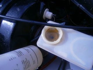
The brake fluid reservoir warning switch continued to puzzle me. It comes on with the ignition; both handbrake and fluid warning switches illuminate, and they both remain on when the motor is running. Letting the handbrake off extinguishes that warning light but not the fluid warning. The simple explanation for this is that the handbrake is on and there's no fluid in the reservoir so I topped it up. Now both lights came on and off with the handbrake- which is better but still not what I expected; I had expected the fluid level switch to remain off when the motor is running regardless of handbrake action. I suspected that the brake switch was malfunctioning- but it was an easy clip-fit to take apart.
 |
| Disconnecting leads from the brake fluid sensor switch in the cap of the reservoir |
 |
| Sensor section of switch: The underside of the lid (left) contains a plunger which rests on the float seen inside the cylinder on the right. When the float is high it pushes the plunger up breaking the connection between the two lugs on the upper side. When fluid level falls the float sinks and the plunger descends closing the contacts in the lid and earthing the brake fluid warning light which illuminates. |
... and inside its a simple float and switch assembly. There were no obvious problems and testing the contacts revealed that depressing float closed them, raising the float opened them so it seems to work. I reassembled and refitted the switch. I studied the wiring diagram some more and I think I have the explanation:
Both H/B and fluid warning lights are fed from a common source (ignition activated post "D"). Each is earthed by their respective switches to turn on the lights. However the two circuits are separated by a diode such that the fluid warning light can earth through the H/B switch
or its own switch, but the H/B light can earth only through its dedicated switch. This means the fluid warning light will come on whenever the handbrake is on, but it can also come on if fluid is lost when the handbrake is off. However, when it does this it will not turn on the H/B light. I tested this using the test plunger on the top of the M/C and it does indeed behave this way. This seems a primitive function compared with more modern cars, but nonetheless it does seem to be how it is designed to work! So this job done.
Bonnet and gas strut
The new struts were supplied as a pair- but even so were cheaper than getting just one from a Lotus supplier. Both ends have ball-and-socket joints and the new strut has sockets so the balls need to be reused. One of these was retained in the bonnet
 |
| Ball joint remaining on the car bonnet |
 |
| Top end of gas struts- old (lower) and new (upper) both have sockets to accept the ball. |
and the lower one had been removed with the strut when it was detached.
 |
| Lower end of gast strut- old strut with ball joint present |
 |
| ball popped out in a vice |
This simply popped out of the old strut and into the new, I greased it with a smear of copper grease. At this point I noticed that the mounting bracket was a little rusty so I've removed that and repainted it, as well as cleaning up the two mounting bolts.
 |
| repainted bonnet bracket. |
The bonnet was very tricky to refit alone- but it is possible using a combination of wooden props and packers. The bonnet, strut mount, strut, washer tube and earthing strap were all fitted successfully.
 |
| Bonnet refitted, I may need to adjust the plunger pins but its closes and pops open ojn both sides so its not that far out. |
Body/Trim extras...
I am guessing that I will never finish fiddling/renovating the trim and I did notice that the glove box has a hole where a blanking plug is missing- I've ordered a couple of 1.2 cm black plugs which will hopefully fit.
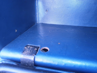 |
| Inside the glove box: Missing plug on left... |
 |
| ... plug present on right. |
The new plug wasn't quite the right size but I covered the plug section with a ring of tubing and it was then perfect and pushed firmly into position. I find these little things unreasonably gratifying- pathetic really isn't it!
 |
| New plug inserted. |
PAS
I summoned up the courage to bleed the PAS. I checked the reservoir was full, started the motor and turned the wheels from lock to lock a few times. Turning, amazingly, did get easier. I topped up the reservoir again. Turning the wheel with the motor off was much harder so there really is some pump assist action. I checked and no sign of leakage so job... I hope... done!
I am now nearing the end of my task list! Never thought I would get here but it really shows itself as the "moment of truth"- Hopefully everything I have done will hold together. I really need to road test the car but obviously with no MOT, its not road legal. There is a limit to what I can achieve on the drive and I guess the first time I get to see how it performs will be on the way to the MOT! In the meantime I still have reservations over the electrics (battery seems to run down) and the cooling system- being sure that its bled and doesn't leak but the otter switch (fan switch) in particular. Although I have repaired the fan and refitted the switch (and it doesn't leak), the fan has never come on and this is obviously concerning. It may simply be that my idling on the drive has never reached 90 deg in the top hose and (Duuuh!!) I didn't check the switch while it was out. I have however ordered a new hose adaptor which will take a threaded fan switch so I can always insert this later.
In the meantime- at this milestone I think its appropriate to look at how far I've come and so here are a few before and after pics of the engine bay....hopefully you can see which is which! Photography has improved if nothing else!


