Search for tasks- type in keywords

Showing posts with label Lotus. Show all posts

Tuesday, 21 March 2017

Installing Hi Torque starter motor, Powerlite RAC415

My motor has always been ponderously slow to turn over. I'm not sure if this is the compression on the motor or wear in the starter but I tend to suspect the latter. As you may recall my early investigations showed that the previous starter motor, as fitted to the car when I got it, was burned out. I presume due to trying to turn over a motor with jammed valves. I replaced this with a used substitute- this turned,  and indeed started the motor, but has always been slow- plus its had a lot of wear during my attempts to start the thing after the rebuild.  It seems to run the battery down very quickly as well, so I believe its taking a huge current- possibly also due to wear. I had always intended to swap it out for a more modern hi torque geared starter and I guess now is the time.

These geared starters are available from several sources- after a bit of a search I settled on a Powerlite RAC415 at £183 from Eurolec Components Ltd. This was some £60 less than others I was quoted.... and it included VAT and delivery! Bargain I think. The unit is about half the size (and weight) of the Lucas 3M100 and this worried me at first but it fits right in.

There are only 3 electrical connections, the battery positive and alternator charging cables (both to the copper stud terminal) and the relay activation wire (red/white to spade terminal). These are easily detached.
Boot over battery power cable

Detaching solenoid cable.

The motor is held on by only two nuts and bolts (17mm) easily undone as its not so long since I cleaned and refitted these anyway.
Starter top mounting...

...and bottom

Mounting the new starter was also easy in that it slipped right on to these two bolts. However there is a slight problem with the position of the terminals. You can mount the motor as I did (pics) in which case the terminal contacts are underneath and awkwardly placed, or you can mount it 180 degrees from this in which case the solenoid section is tight up against the block.
New motor in position


Look at all that space between the starter and oil filter!


I wanted to maximize space around the starter in the hope that I could  avoid the solenoid obstruction that prevented me from clipping up one of the airbox fastenings, so mounting it "terminals-down" seemed like a good starting point*.

I won't pretend that this isn't awkward, the dip stick is well placed to obstruct and you have to do the job largely by feel. I also think that at some point the cabling from the battery has been shortened and the cable just wouldn't reach the terminals in their new position. I may be able to adjust this later when I can get under the car and trace the cabling back, but for the time being I decided just to lengthen the cable. I used a crimped cable joiner and new eyelet to extend the cable. Fortunately I had lots of this stuff left over from a similar exercise in the battery compartment (see my previous post here).

I connected up the new motor and tried to start it.

What a revelation!! The difference is indescribable. The motor skipped over like a fairy in springtime and started immediately. I've never had a cranking speed like this and so I find myself  VERY impressed. If you don't have a hi torque starter already I can whole-heartedly recommend that you get one!!
* Although there is more room- sadly there is not enough room to solve the clip problem. When fitted like this the tensioner clip cannot be fastened because the top of the starter is in the way.
Fitted incorrectly, both hook and tensioning clips are on the outside the the starter, the lower tensioning clip should be "block-side"

If you wish to use this clip then its necessary to ensure that the tensioning clip is engine-side of the starter whilst the hook clip is over the motor and available for the airbox when you fit the airbox itself. If fitted as described the clip can be used although its advisable to fasten this one first.

Monday, 6 March 2017

Door hinge: fitting a grease nipple

My doors are in need of some attention although not yet critical. I have already covered lock and door card issues but there is more to consider. The door beams are showing surface rust and much of the shoddy powder coat (or poorly applied paint) has come off; preparation here seems to have been lacking and for a top end car shouldn't this be galvanised? They need stripping, treating and repainting plus a generous application of waxoyl wouldn't go amiss! Similarly the glass frames are showing some rust and may need repair or replacement: new window channels would be great and I'd like to service the window motors and mechanism. Luckily I don't think anything is past salvageable yet and its certainly my intention to tackle this in the summer... after the car is back on the road. At the moment access is poor but I don't want it getting worse so I will tackle the hinges and any surrounding rust now.

The doors in my car are fairly stiff to open: the passenger door being the worst. This is fairly typical if they don't get much use but if left unattended the pins can seize solid and start turning with the door. This can elongate the holes leading to door droop... and droop is never a good thing!! My pins haven't seized and the doors don't drop. I want to keep them that way. One useful mod I've seen referenced is to fit a grease nipple and force fresh grease up inside the hinge tube and (hopefully) through the top and bottom bushes inside which the door pin swivels. This job is  also best done when the doors are off and the pins out, but I don't want to wait and making this mod is in my book an insufficient reason alone to take the doors off!

The three big problems here are to make sure the the new nipple wont foul the A pillar as the door closes; that the nipple is accessible for greasing when the door is open and that swarf is prevented as far as possible from entering the hinge tube as it wont get removed until the door is stripped.

Firstly, I tested grease gun access and then stuck a blob of blue-tack in the selected location making sure it was at least as tall as the projecting part of the nipple. I could then close the door a few times and check that the blue-tack wasn't squashed. Having found a suitable location I centre-punched it and drilled it with a 5.5mm  drill to penetrate into the pin chamber. The location turned out not to be that critical but I decided to make the hole 7cm down from the top of the hinge and adjacent to the weld seam as shown.
Centre punch 7cm from top of hinge in line with weld seam.

5mm hole drilled.
I cleaned up the hole and collected loose swarf with a magnetic pick up.


I tapped the hole M6 using a taper tap to start followed with a flush-ended plug tap to get through the metal without hitting the pin. However tapping wasn't straight forward because access was limited between the door and pillar. Since long shank taps are expensive I dont have one! I eventually managed to fix the problem by tapping the end of a chucked tap wrench to take a M6 bolt which I then screwed in and could then turn the tap using a socket on an extension rod in a ratchet handle.

Hand tap wrench- remove handle...

... tap end and insert M6 bolt

Assemble ratchet handle and extn rods and socket to turn tap.
Once tapped I could screw in an M6 nipple and pump in some grease.


The door action was markedly improved! The rust around this area is really only surface but to be sure I removed loose paint and treated the rust beneath with "Metalmorphosis" chemical rust coverter and left it to cure overnight. Excess removed with meths.


I then repeated the process on the driver's side- now that the tap handle was sorted it took barely 10 mins and again the door action was greatly improved.

Drivers door- door hinge drilled and tapped in same position...

... and new nipple inserted.
I also treated the rust for re-painting  later.

Rust treated and painted- improvement!


Thursday, 2 February 2017

DHLA45 enrichment device (choke) and acceleration pump

Apologies to my Reader, I had difficulty getting my head around the operation of both the enrichment device and the acceleration pump. Neither are described well in Mr Hammill's book and although the information is out there its a bit scattered. I tried to get my head around it before contemplating interference with either system and below is the result of my deliberations. I am reasonably happy with it but the usual provisos and warnings apply! The work I did on the pump is described with pictures after I've tried to describe the principles of operation.

Enrichment device:
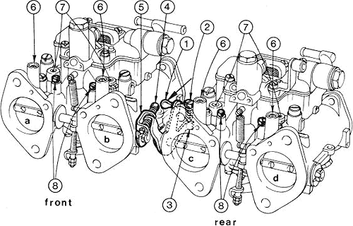
The enrichment device (or choke in UK parlance) is contained partly in the lid of the carb (control mechanism) and the body (fuel/air passages). It is held to fail so rarely that servicing it isn't really described well anywhere. I have lifted these diagrams from the Laverda club but the description is mine.

Overview of carbs, enrichment device control is located in the towers visible on the lids and capped with a large brass hex plug.
The official Dellorto exploded diagram is below... 
Dellorto diagram- exploded view DHLA 45. Choke control mechanism shown top left and the tower piston top centre.

Choke in operation. 
The choke operating system in the carb top consists of a rotating lever/cam which raises or lowers a piston contained in the tower. Operating the choke control pulls on the lever (39) which rotates the eccentric pegged shaft into a groove in the choke piston (18) contained in the tower, raising it against the pressure of the spring (19). This piston is very similar to the piston contained in an ordinary ball valve; it has fixed into its lower end a blank rubber (nitrile?) washer. When the choke is closed this washer is held by spring pressure against the choke diffuser (116, but not indicated in this diagram) opening in the lower carb body preventing air from entering, when the piston is raised as above, the washer is raised allowing access to the diffuser.

The effect of raising the choke is shown below using a diagram from the Laverda club. The piston (7) is raised and fuel is drawn directly from the float chamber through the starter jet (12) and its associated emulsion tube where it is mixed with air at a richer than normal ratio. The mixture passes into the choke diffuser  at (8) which splits it into two streams. These pass down separate passageways (9) to exit in the throat behind the butterfly. This provides a direct and low resistance path for a richer mix to enter the throats behind the throttle butterfly (10). 


Laverda club DHLA45 diagram of choke in operation. Fuel from the float chamber (shaded) is drawn up through the starter jet (12) and emulsion tube (11). It is mixed with air and this mixture can enter the choke diffuser (8) and associated passageways eventually to exit behind the butterfly at (10)
 At normal running (full throttle shown below; again taken from the Laverda club) the choke piston is held down by spring pressure- access to the choke jets and passageways is therefore closed.  Fuel is drawn  up from the float chamber through the main jet (37), mixed with air at the normal ratio in the chambers above and eventually discharged into the Venturi tube (38)  in front of the throttle butterflies.


As everyone says, the enrichment system rarely gives trouble, and when it does its usually wear iķn the washer on the bottom of the piston. This would allow richer mixture to enter the motor at all times leading to very rich running. Having considered this I doubt it could be the explanation for the flooding I see in my car but there is a simple way to test; since the control system is contained in the carb tops you can simply swap them and see if the problem moves with the top. In my case it didn't so I could exclude the washer as a problem in my case- result!

Should you need to change the washer though then its not straightforward as I can't find this washer listed separately as a replacement part  by any of the Dellorto suppliers. I suspect you are supposed to change the whole piston. As an alternative you could try removing the washer and simply turning it over so that the unworn side faces the choke diffuser, but I am pretty sure that a suitable replacement could be sourced if you know the size and take care to get fuel resistant materials. However as mine isn't damaged I'm not going to remove it to measure it!

Acceleration Pump
Once again Mr Hammill says little about the acceleration pump apart from advising everyone to leave it alone. However, this has to assume that its correctly setup beforehand and in my case I can't assume that. The pumps of course are designed to squirt pure fuel (not a fuel air mix) directly into the carb throats and as such are obvious candidates for the flooding I now see in my carbs.
Here is my interpretation of the pump and its operation which I found isn't immediately obvious... So "Caution" Dear Reader, this may not be right! The acceleration pump is shown between two diagrams below so please dodge between them. - Sorry.

The acceleration pump consists of a spring (75) loaded diaphragm (76). On the lower side of the diaphragm is a brass boss which is in contact with a pivoted operating lever (72). As the diaphragm is pushed down by the spring it in turn pushes down on the lever at the pump end which raises it at the other.
The other end of the pump lever interacts with an operating rod shown below (90). This is attached to the throttle spindle (101) at its top end whilst its lower end is threaded. The rod is moved up or downwards as the  spindle rotates. However this rod does not simply push the lever, instead it passes freely through  the hole in the end of the lever (72) shown above. Consequently, operating the throttle would have no effect on the pump lever were it not for a spring system (71) mounted on the rod above the lever. The spring is restrained at its upper end by a washer (62) fixed to the rod. The bottom of the rod is secured below the lever with an adjuster (73) and lock nut (74), both 6mm size.


This means that as the throttle is opened, the actuating rod is moved downwards through the pump lever. This compresses the spring on the rod between the fixed washer and the lever itself. As this spring is compressed it eventually exerts enough force to overcome the spring holding the diaphragm down. At this point the spring pushes the rod-end of the lever down forcing the diaphragm up and pumping the fuel above it into the acceleration circuit in the carburettor body. The amount of throttle movement needed to compress the rod spring enough to move the lever can be adjusted using the rod-end adjuster to set the pre-load on the rod spring.

This system has three advantages; Firstly the rod is moved by a constant spring pressure regardless of how fast you press the accelerator. Thus petrol will be fed at an even rate. Secondly by relieving the pre-load, the amount of throttle movement needed before the pump operates can be increased. This means that the pump can be set only to operate when force-full acceleration is required; not during everyday driving. This avoids constant pumping which would over-enrich the mixture leading to poor running and increasing fuel consumption. (There are quite a few sites out there which state that the pump should operate immediately the throttle is used- this doesn't seem sensible to me but may relate to race tuning- as I said this is all just my opinion).  Finally,  the diaphragm spring  depresses the diaphragm but pushes the brass boss down onto the end of the adjustment lever which prevents it from moving further. It could move further down if the rod end of the lever is raised lowering the lever's protrusion below the diaphragm boss. This means that as you screw the adjuster up or down to adjust pre-load on the rod spring you also affect the level to which the diaphragm can settle against the pump lever. This affects the volume above the diaphragm when retracted and thus the volume of fuel that will be pumped out through the system when the pump operates. Consequently stroke volume and pre-load are inter-related and its the balancing of these two effects which results in good performance.

The upward movement of the diaphragm pumps fuel through the carb as shown below. 


In this diagram the spring (30) and lever (32) help to move the diaphragm (31) downwards. This draws petrol from the float chamber above via the non-return valve (25) into the pump space. This diagram shows the pump at the end of a stroke; the diaphragm is already fully raised and the pump chamber almost empty as the fuel is in transit. Since back-flow to the float chamber is prevented by the one way valve (25) the diaphragm pumps fuel out vertically upwards past the check valves (24). These consist of ball bearings that sit in a taper blocking the tube. The bearings are held down by bar weights above. When the pump acts, fuel pressure increases and soon overcomes the weight of the bars forcing them and the ball bearings up the tube and opening the passage to fuel. This pure fuel (NB not a fuel air mixture) is then pumped through the carburettor passages to exit at the pump jets (26) where it mixes with the stream of fuel/air mix being drawn through the Venturi by the open throttle.

Adjustment:
Adjustment aims to set the volume of fuel pumped in relation to the point at which the pump operates. In general operating the pump through a full stroke should move around 400ul of fuel. This is generally measured using a special rig and pumping the throttle 20 times (measured output volume 8ml - although I'm not exactly certain that this shouldn't be 4ml per jet, 8ml per carb).  This is balanced against the amount of throttle opening needed before the pump operates- too little and fuel consumption will be unacceptably high, too much and the engine will hesitate under acceleration. Although its probably possible to rig up a test stand to measure the fuel flowing through the jets, its this second, very practical consideration that I think is more important- and can be set (eventually) through road testing. In my case I'm concerned that the carb flooding I observe is a fire hazard that will prevent me from running the motor for long periods let alone conducting a road test! Obviously the pumps are used to squirt fuel into a stationery motor when starting up and this fuel has to go somewhere. If the motor doesn't start- or if more "pumps" are necessary then this excess would presumably hang around in the barrels until such a time as the motor warms up and the intake removes the excess as vapour. This is pretty much what I'm seeing now so I set about examining the state of my pumps:

Immediately I found that the acceleration pumps did not behave as I had expected: Gentle (small) throttle openings immediately pressed on the actuating lever and caused petrol to drip from the pump jet. Excess petrol is needed only in rapid acceleration and so this behaviour seems likely to induce flooding. I removed the carbs to examine them more closely. The activation rods were set very differently.
Acceleration pump activating rod free length below locknut- rear carb


Acceleration pump activating rod free length below locknut- front carb

The forward carb had barely 2 mm of adjuster rod visible but the rear, which has the greater flooding problem, had almost 6mm. This would give a much longer actuating lever stroke and thus deliver more petrol when the accelerator is pressed. This will also have increased the pre-load on the spring such that slight movements of the rod would be reflected immediately in lever movement by the already-compressed spring.  Des Hammill does state, buried away on page 102 of his book, that adjustment should give less than 8mm of threaded rod below the lock nut, and elsewhere Tim Engel suggests that 2-3mm may be a good starting point. Both my carbs are in this range. Although I was concerned that they had different settings, its not impossible that they could (and possibly should) have different adjustments; spring strengths may differ or there may be some other problem that was addressed by extra fuel supply. In my case I have already cleaned and rebuilt the carbs and the motor, and I will change the springs so that these too are new, so any wear-related differences should have been eliminated. This does make me think that any such differential settings required in the past might now be outdated.

Accelerator pump spring change
The new springs were narrower than the old and had a free length 0.7mm shorter.
New spring left, old right, appx 0.7mm difference in free length.
They were easily swapped although its necessary to loosen the pump retaining screws to get enough arm movement to slip the actuating rod out. The new springs are installed with the widest end on the lever.
New spring compared to old in position

6mm locknut and adjuster removed- insufficient clearance to slip the actuating lever off.

Loosen the pump base plate springs to provide extra clearance to slip off the lever and replace the spring.
I wound up the adjusting nut to leave 5mm of thread exposed and then screwed on the lock nut. This left close to 2mm of thread below the nut as before. I chose to measure the distance from the rod end to the adjuster because this is larger and so more accurately measured. Also its hard to measure the lock nut as the dimension changes when its snugged up to the adjuster and its a bind to have to keep tightening and un-tightening to adjust.

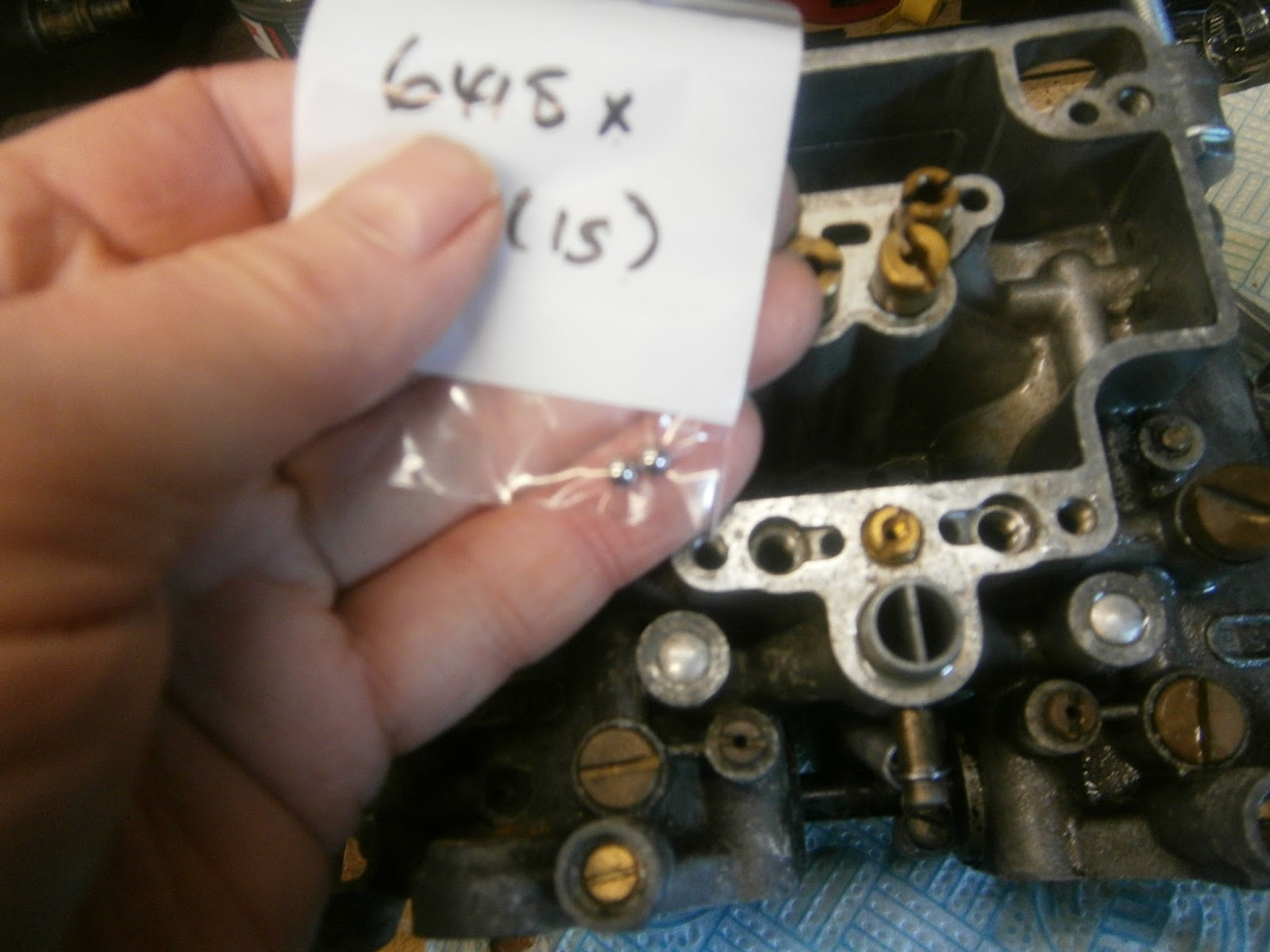
Having swapped the springs I also fitted new bearings in the acceleration pump.
New balls please!
I was then able to reassemble the carbs and fit to the car.

After assembly the car started relatively easily but running was very rough, apparently missing or spitting back occasionally, and rocking rather a lot. BUT.... on the credit side the excessive fuel in the rear carb has GONE (Hooray!!!) and I think therefore that the acceleration pump was the problem. I might have found this sooner were it not for Mr Hammill's advice. I know that this is well meant, and probably sensible if your car is relatively new (or at least well maintained!). In my case, it simply made me think the accelerator pumps were far too complex for me to fiddle with! Of course I still have to set them for the correct performance so this warning may yet come to pass, but at least I will be able to run the motor now to check.

So like a Knight of old I have now overcome the acceleration pumps in single mortal combat! Sadly, I cannot yet retire from the field covered in glory: there is still the problem of the excessively rough running, rocking/shaking and spitting of the motor- I appear to have wounded the beast but not yet totally vanquished it because running is far from acceptable! The story of the misfire and what was actually causing it is continued here!


Thursday, 26 January 2017

Battery, terminals, case and cables

  • Apologies dear Reader- I have reworked this blog entry to remove much of the repetition and bitterness over incorrect materials and wasted time!


    The battery in the Excel is a type 067 but type 027 has the same dimensions and offers improved performance. I bought an Exide version for about £50 which should let me use the original battery strap and cover with its newly installed replacement turnbuckles.

    I also have a problem with the battery cables- largely of my own making! I had got quite fed up with constantly attaching and re-attaching the battery terminals, so I removed these (the neg was soldered and had to be cut off) and fitted a pair of Halfords quick-release terminals. This was an error! Those terminals do indeed grip and release the battery posts in a convenient fashion; but the grip to fasten the battery cable is very poor. In general there are three acceptable ways of fastening a battery terminal: Solder, Crimp or use a screw on terminal where two screws penetrate the conductor wire. Soldering is best but I worry about doing this in position. I don't fancy naked flames anywhere in the boot or near the tank. Crimping is to my mind safer on the car, and seems to be of two types- a socket that is crimped around the wire using a hexagonal crimp, or two wings which are folded and crimped in on top of one another using an Anderson crimper. Crimped terminals are sometimes soldered as well giving a good solid joint with excellent conductivity. Sadly the Halfords terminal uses none of these methods. Its a simple screw clamp rather like the cable grip found in a domestic plug: The screws are puny and don't penetrate the copper conductor. If the cable is under any strain at all it just slips out of the clamp!
    Quick release battery terminal- Wire clamped in grip plate by a screw at each side- its pulled out again

    Top view
    "cable grip" style very puny clamps

    The negative cable provides the only connection between battery and car; everything electrical earths eventually through this contact so its vital to keep it in good order at both battery and chassis terminals.

    At the battery end, my cable is now just a few inches too short to reach the terminal without strain and keeps pulling out. I can either replace it or extend it, and as extending it is cheaper I will try that first. Lotus used copper cored  battery cable. The copper interior is 8 mm diameter and the cable including insulation is 10mm diameter. I realise that this gives a predicted copper area close to 50mm2 but I ordered some of that and it was far too big... the wire seems to be 35mm2..? This I later discovered is a common confusion. Even some suppliers will send the wrong size cable. As a working assumption I now assume all multistrand cable is actually the size below its measured and calculated size because of the gaps between the strands, although the disparity does reduce as the cable size decreases. So a bundle sized at 70mm2 is probably 50; one sized at 50 is probably 35 and one sized at 35 is probably 25! I ordered new cable, solder-or-crimp-on terminals for both positive and negative battery connections and a butt joining  sleeve to connect a short extension to the cable. I also ordered new terminal covers as my existing were split.

    Battery Post Terminal
    I bought a Chinese made hydraulic crimper from Ebay- seems to be similar to the harbour freight model although 8 ton rather than 10. This was very cheap at £15 and should be fine for the occasional use I envisage. I also bought some 35-50mm terminals both battery bolt on type and eyelet fixings.
    8 tonne hydraulic crimper

    Butt joining tubes

    From the foregoing it should be clear that it was my intention to do this job "properly". In the event, it didn't turn out that way. Firstly I trimmed the wire to fit the new terminal-cutting back the insulation over the length of the socket.
    Insulation stripped from wire to depth of socket

    I could then slip on the terminal cover and the heat shrink needed to finalise the terminal...
    ...and then I tried to crimp it! There are several videos online and the crimper I bought is similar to that sold by Harbor freight (USA) and others- although mine is only an 8 tonne version. Most videos are from the US and state all wire sizes in AWG- for both wire and terminals. Great if you buy your materials in AWG, but in the UK they are sold by cross-sectional area.

    My initial experiences weren't good. This was largely due to mismatches between cable, fitting and die size. Although a 35 cable does fit easily into a 35-50 post terminal I found that it was virtually impossible to crimp tightly enough to hold the cable and when I did so the terminal promptly fractured. I will investigate the right way to crimp these terminals but in the meantime I was able to reconnect a new bolt-on type terminal. I also fitted the new battery and  and although the cable is stretched, it could reach the new battery (Exide Premium EA612 Carbon Boost 61Ah 12v Type 075). Thus for the first time I was able to fit the battery carrier, cables and cover to finally neaten up the boot.
    Installing new battery and restored clamp- new turnbuckle female halves (these are cheaper if you buy Range Rover turn fasteners)

    ... connecting...wire a bit tight still.

    Case installed
    Well it looks nice and the starter motor turns with more ooomph now!! The cable is still too short and once I get more terminals and solve the crimping problem (or solder the post terminal on!) I will extend it to make a more comfortable fit. I will update this blog at that point but since I'm also waiting on getting the car up on ramps to get at the chassis connection and exhausts (see below) I thought I'd post now and update later!

    Crimping Revisited!

    For what its worth my experience:
    What follows has been gleaned from my extensive experience of at least a week, two lengths of cable purchased and about half a dozen terminals destroyed! It may help you, but bear in mind it may be/probably is wrong! If anyone can supply a more accurate guide then I will be delighted- send me a comment or PM me and I will be happy to put it here.

    I had several attempts but this is what worked for me... If you don't want to read my painful voyage then here is the conclusion!

    • Use SEIWA tin plated brass terminals
    • Use 7mm ID terminals (25mm2) and connectors for both 35 and 25mm2 cable.
    • You may need to neaten a 35mm2 strand bundle with a 16 or 10 die before it will slip in.
    • Crimp battery post terminals with a 25mm die
    • Crimp 35mm2 cables in butt and eyelet terminals with a 25mm die
    • Crimp 25mm2 cables in butt and eyelet connectors with a 16mm die.

    For anyone more interested in what I actually did then the account follows...

    Post terminals- I bought tin plated brass SEIWA terminals in 2 sizes specified by internal diameter 7mm and 11mm from nnc-tuning (eBay). I did try other types but they cracked- possibly due to my error. These worked and I'm sticking with them in future. The 11mm was really too big for use on this car.


    Two post terminal sizes, sold by ID; 11mm on left, 7mm on right

    Smaller terminal ID 7mm


    and OD 11MM

    I tried to ID the cable size I was working with- this is the  cable I was sent as 35mm2. The inner bundle diameter is 6mm and the cable outer diameter (inc insulation) is about 8mm. This gives a calculated area of the core as 28mm2 and I suspect its really 25mm2 cable. In any event it would slip firmly into the smaller 7mm ID terminal with minimal compressing

    Internal diameter of copper bundle 6mm. 

    External diameter inc insulation 8mm.
    Cable inserted into 7mm terminal
    The cable I had bought would fit comfortably into the 7mm terminal, but how to crimp? The recommendation is to use the same size die as the cable area, but perhaps its better to consider the terminal you are about to use. This was a 7mm post terminal intended for 25mm2 cable. Test-aligning a 35 mm2 die showed that it wasn't likely to compress the fitting much and the 25 gave a better looking gap and so should compress well.
    35mm die surrounds terminal- little compression is obtained when the die is closed 

    25mm die still has room to compress
    I therefore inserted the cable into the post terminal...


    And crimped well using the 25mm die pair

    I slipped on the heat shrink and cable terminal cover, shrinking the tube


    I then crimped a 25 sized butt join connector onto the other end. This is a thin walled terminal and the 25mm2 dies seemed too small for this application. I therefore used a 16
      25mm cable butt connector crimped onto the other end using a 16mm die.

    This is where I got yet more evidence that the 35mm2 cable supplied was actually 25 since the cable in the car was larger- it was too large to fit into the terminal unless pre-crimped. I squeezed it with a 10mm die to neaten the ends.


    ...and it then fitted nicely. I used a 25mm die to take the larger cable into account. The join was then...
    Butt joint- 16mm crimp to new cable (upper) and 25mm to existing (lower)
    ... covered in heat shrink...
    ..to make a neat butt join.

    I could then refit the battery case- its a better fit now that the cable has enough length to bend naturally onto the terminal without lifting the carpet or displacing the battery cover.

    Overall its now my view that crimping is difficult to get right and confusion in cable sizing is largely to blame. This is probably why there are a lot of soldered and bolted terminals out there. I am not happy that I have ended up with a smaller diameter cable connecting to the battery and I will probably change that later. For the moment I'm going to stick with it as a week spent buying wrong cables and connectors is too unpleasant to repeat just yet. It seems to me that the US system of marking and matching terminals to cables using  AWG could remove much confusion. It would also help if UK cables were similarly embossed with their CSA.

    Chassis Connection.
    The chassis connection is made at the rear underneath the car. The cable penetrates the body, exiting the boot at the front and there are a number of grommets and sheaths to prevent it chafing. It terminates in an eyelet bolted on to the chassis. This seems an obvious place to corrode and I'd like to check and clean the contact under the car. This attachment is apparently accessible via the rear right-hand wheel arch.  I don't know what mine is like because I haven't found it yet! I will need to raise the car to get at this connection so I'll leave the underside work until I can drive the car up onto ramps and tackle the exhaust at the same time.

    ... on a different tack...
    I will just note two unrelated observations that emerged from my considerable time spent in the boot. These will need tackling in due course.

    Firstly, the wiring loom crosses the boot and passes through the carpet at the top right above the battery. It then crosses above the battery to connect with the rear light. However there seems no way to fasten it securely to the top of the boot as it passes over the battery and the self adhesive clips used previously have long failed. I'm having to hold it out of the way in the picture above. This means it looks anything but neat! I'm not sure what would be best to hold it up out of the way and out of sight but I will see what I can find. Sadly as this is the outer skin of the car I can't use a screw fastening.
    Wiring loom passing above battery. Old failed adhesive clips present
    Secondly,  I found that there is a very brittle tube that seems to run around the boot and dives under the carpet on the the RHS. In my case this is not (or no longer) connected to anything and its somewhat mysterious. I did identify this and describe it here.

    Brittle plastic tube underneath carpet on RHS- apparently dipping down to leave boot at rear right corner.