Search for tasks- type in keywords

Tuesday 28 February 2017

Carburettor setup and synchronisation.

I will not pretend that sorting out even the basics of these carburettors has been simple. I have been stuck for some 3 months chasing fuel drippage, misfiring, not firing at all and sparking problems! Since these problems prevented me from running the motor I wasn't been able to set timing or balance the carburettors properly until some semblance of safe and reliable running was achieved. In retrospect I can say that its now clear that my carburettor problems arose from 3 causes.

Firstly, float levels were too high at 12mm. This tended to cause overflow. Resetting to 15mm gave a lower than expected fuel level (consistently around 30-32mm) but has stopped the overflow.
Secondly, the acceleration pump on the rear carb was set for a larger pumped volume than that on the front- and probably rather larger than required. Resetting this has reduced excess fuel supplied during starting.
Thirdly, a poorly adjusted carburettor linkage had led to misfiring/not firing in cylinders 1 and 2
And - superimposed on all of this was a damaged AB14-to-pickup connection lead resulting in sporadic loss of spark which hopefully I have also now fixed by fitting a new WM12 connector and lead. I can replace this pickup entirely and new ones are available from H&H Ignition services at £40.

If we assume that I have at last sorted these problems then its time to optimise the carburation ... so, finally, I can move on! I did want to do this job properly- in the end I don't think I did, but here at least is my research and the reasoning behind my adjustments. Please feel free to comment (and dare I say help!).

Setting up the carbs involves adjusting and equalising the amount of air drawn in through each barrel due to the induced vacuum of the motor, synchronising the movements of the butterflies in each carb so that this vacuum/air intake will alter equally in each barrel as the throttle opens,  and adjusting the air/fuel mixture at idle. Only the idle mixture is adjustable, the mix at higher throttle openings is governed by the various jet sizes installed. After adjustment the carburettor should give a smooth idle and this is re-set close to 600 rpm to complete the process
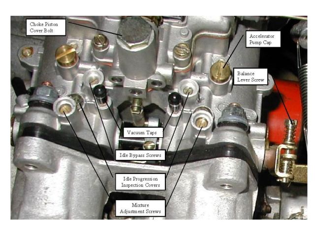
To achieve all this a DHLA45 carb has 4 adjustments that can be altered:
  1. The idle mixture control screw (1 per barrel, 4 in total).  Sets the idle combustion mixture individually for each barrel. May be covered by plastic tamper proof caps. 
  2. The air (or sometimes "idle") bypass screw  which allows the 2 barrels in one carb to be balanced one to the other (1 per barrel, 4 in total). Maybe covered in metal tamper proof caps
  3. The throttle synchronisation mechanism- 1 adjustment screw that controls the the opening of the front carb relative to the rear carb and allows one carb to be balanced against the other.
  4. The idle speed screw- affects the throttle lever rest position  for both carbs and thus the motor's idling speed (one screw)
These adjustments are shown below in a picture taken from "Richards place" I borrow it for clarity although it shows vacuum takeoff taps fitted with spigots and caps, whereas mine are blocked with screws. Similarly the air/idle bypass and idle mixture screws are shown here as exposed although mine were all covered by anti-tamper plugs. The idle speed screw isn't shown as its on the other carb.

A quick Google search revealed dozens of articles about the setting process.  I have concentrated on 5 as below. They are meant for different vehicles but the carbs are basically the same:
I don't want to go through these methods but I think they boil down to two approaches which differ in how the air bypass screws are used.

In the first approach, the idle control screws start off closed so that the weaker barrel can be identified. The idle bypass screw on the stronger barrel is then opened to admit more air and so reduce vacuum to match its weaker companion. When fully adjusted only one idle screw will be open in each carb- the second will be closed and that barrel effectively functions as a carb without such an adjustment.

In the second method all idle bypass screws are open at the start of the process and progressively adjusted (opened?) until balance is achieved. At this point all idle bypass screws will be open to some extent and so in every barrel there will be air coming past the butterfly and through the bypass system.  Since some air comes through the bypass, this means that at any set idle speed the butterflies will be closed more than is achieved by the first method. This approach is more complicated but is said to give better control over emissions.

Both methods require that the butterflies in both carburettors move in synchrony as the throttle is pressed. This means ensuring that they are in the same position at at least one point in their movement. This match position can be set either functionally using vacuum equalisation (when closed);  or physically as they move by checking that they pass a fixed point (such as one of the progression holes) together. If the spindles and butterflies are in good condition then it will make little if any difference where/how you set this match, but if the spindles are bent or the butterflies worn it may well do so. In this case setting for balance at throttles open may be preferable for smooth driving at the expense of smooth idle.

Similarly both methods require optimising combustion and thus reducing emissions. Emissions are measured either directly using a CO monitor, or indirectly with a colortune or by monitoring vacuum in that carb. Given that there are 4 mixture screws and the only domestic exhaust gas analyser is the Gunsons Gastester which I have found to be wildly insensitive even when used on single carb cars, I suspect this isn't practical. In fact I found the other two methods relatively ineffective as well (see on) and this remains the most significant problem I found in balancing.


My Approach:

Dellorto dont want me fiddling with these settings or they wouldn't cover them all with anti-tamper plugs! 'For once there is no sign of the bodging hands of the LBPO, so I would be only too happy to leave them alone but the car has had a chequered history and channels may be clogged or blocked. All the same I didn't want to risk upsetting what could be a perfectly adequate setting, so I wanted to check whether the preset adjustments were still applicable. I think that if they are correct, then it follows that balance will already be set within each carb. In other words both barrels should already be matched when idle mixture screws are adjusted to give maximum vacuum; effectively setting the idles for max vac should show the barrels of each carb to be matched and all I will need to do is adjust the carb linkage to equalise vacuums between them- and maybe check with the colortune that I'm getting good combustion. If the barrels do not match then the air/idle bypass setting may no longer be appropriate and I will need to start from the beginning.

It was simple enough to warm up the motor and connect the Carbtune spigots in place of the vac blanking screws and connect up the unit. 
Vacuum blanking screws replaced with plastic carbtune spigots...

... in both carbs.
The pulsing effect was v bad until I realized I was holding the unit upside down (Duhhh !) and matters improved after that! The rear carb barrels were quite similar, but the barrels in the front were out both with each other and the rear carb. 

Here was my first surprise.... all the methods I have read speak of optimising the vacuum using the idle mixture screws as the first step, and readjusting them with this screw throughout. I was shocked therefore to find that in my hands the idle mixture screws had virtually no effect on vacuum at all! I tried a colortune but they had little effect on that either. Screwing them all the way in did lead to a misfire and a stall  but there was practically no effect until the motor became non-runnable.  I did find that the rearmost idle mix screw seemed to leak and gave a steady reading only if pressed down. I took that one out and found it lacked a spring completely. 

Look Ma- no spring! Even though...

... springs were present in all other idle mix screw holes
All the screws were a bit scratched and the "O" rings looked worn although I doubt any were actually unserviceable. Nevertheless this might be part of the explanation?
New idle mix screw left- old one right

In any event  I decided to change all the screws,"O" rings and washers, and of course to fit a new spring in barrel 1.
Nice new bits from Eurocarb

Since the carbs didn't seem to be balanced, I would have to deal with the idle (or air) bypass screws, so I removed their anti-tamper plugs (drill through and lever off) and tested their settings. The rearmost bypass screw on each carb was fully closed so it appears my carbs have been balanced previously by the former one-air-screw-shut approach. The second screw was positioned at 3/4 turn (rear carb) and 1/4 turn (front carb). For completeness I replaced the O rings on all 4 of these screws as well and cleaned out the bypass passages with carb cleaning spray. All the screws looked fine apart from the forward screw in carb one which seemed to have suffered some form of combustion effect. The screw was darkly discoloured and pitted and I may need to replace it eventually in the meantime I swapped it with one of those which had been fully closed.

Air bypass screw from front carb- seems to have been burned.
I reassembled the carb and ran the motor up to temperature again to start the balancing process. However, having made these changes there was still no obvious difference in idle mixture screw response and the idle screws still had little effect. This is new to me: I am used to adjusting simpler motorcycle carburettors and in that case the idle mixture screw certainly affects combustion, so before I went on any further, I tried to get my head around it. This is what I now think- 

My two-penneth...
The difference between these DHLAs and simpler carbs are many- but one obvious glaring difference is the presence of progression holes. These are meant to be "progressively" exposed at low speeds as the throttle opens, they supply extra fuel and avoid over leaness at low throttle. All the balancing methods I have read assume that all progression holes will be closed when the motor is at idle... or as they put it the butterfly will be "manifold side" of the holes. However,  in my case they were not! Having checked with the forum others find a similar thing too. Even when the idle speed screw is backed off completely, and thus the throttle fully closed, the throttle butterflies return to a position across the first progression hole. Ok this may possibly be closing it off, but the motor wont run like this and only a few turns on the idle speed screw would open the first hole. This is seen clearly using my endoscope to peer up through the progression holes (cap removed) from inside the carb.
Progression holes from inside Venturi... only 5 are visible, the 6th is blocked by the butterfly or open to manifold side. This picture taken with no idle speed screw adjustment at all and butterfly at full stop position.
The working of the progression holes and idle screw is shown below in a diagram taken from the Laverda owners club. For idling- fuel is drawn up through the idle jet (20), mixed with air coming from the channel (19) in the emulsion tube  and fed out to the idle mixture screw outlet (22). On the way this mixture passes the progression holes under the plug (23), and provided these are all closed by the butterfly(13), or missing entirely as in a simple carb, then all of the mixture is drawn out past the idle mixture screw by the vacuum in the manifold. Its important to note that the idle mixture screw- despite its name, doesn't control the composition of the fuel/air mix passing by it, but in this simple case it will control the quantity of this fuel/air mix that flows past it. Opening the screw will allow more fuel/air mix in to combine with throttle-metered air entering from the front of the carb through the Venturi, so at any given throttle setting the idle mix screw can regulate the amount of fuel in this final combustion mixture.   


But... what happens if as in my case one of the progression holes is uncovered? Now the idle mixture can exit to the motor through two routes: past the idle screw as before but also through the open progression hole. Its important to note that its the same mixture being drawn though both exits by the vacuum inside the carb. Adjusting the idle mixture screw can regulate the amount of fuel/air mix that passes by the screw just as before, but as the screw shuts, more mixture will simply be drawn in through the progression hole and the total amount admitted will not necessarily be changed (see small inset diagram above). In practice there may well be some effect on the total drawn in since the vacuum in the carb will have different strengths at the prog hole compared with that at the idle screw, but this is subtle compared with the situation in a carb lacking prog holes and may explain why I found that the idle mixture screw was essentially functionless.

If what I have said above is correct then it follows that the idle mix screw will be most effective when the throttles are as closed as possible- perhaps completely closed. This would mean that the idle speed screw is set almost out and the air required to allow the motor to idle will need to come in part - possibly a large part, through the idle (air) bypass system. In other words the second adjustment method would seem to be preferable. This would give a responsive idle mixture screw which could be used to regulate combustion in each cylinder at idle to give the lowest possible emissions. In time perhaps I will try this approach, but given that my carbs appear to have been balanced by the former (one-air-screw-closed) method I decided to try that first.

Adjustment:
I disconnected the throttle cable and set the motor to idle around 800 rpm using the idle speed adjustment screw and warmed the motor to temperature. I then stopped the motor, fitted the Carbtune spigots and connected the unit up. I then closed the air screws on all carbs and restarted the motor. The method calls for maximising the vacuum in each barrel using the idle mixture screws- I tried that but found little effect (see above).
I then opened the air screw on the stronger barrel in each carb to reduce vacuum to match that in the weaker barrel of each carb. The air bypass screws did have an effect and it was possible to set the pairs equal in each carb.  I could then set the front and rear carbs to match using the carb synchronisation screw. I had synchronised the butterflies physically in the past and in fact this was very close to synchrony achieved by matching vacuum. Finally I reset the idle speed and rechecked the idle mixture screws- again with little effect.
At this point the carbs were all balanced by vacuum, but the motor had a misfire. This I assumed was due to incorrect mixture setting, so I adjusted the idle mixture screws and found one that clearly improved matters. In order to check this adjustment across all cylinders  I used a pair of colortunes to check 2 at a time. These were installed in cylinders 1 and 2 or 3 and 4 and thus checked the output from both barrels of one carb at the same time. This also let me compare the colours in both cylinders.
Checking combustion colour in cylinders 3 and 4

Flash picture of above
 I don't think the photos really show the colours but it was hard to see them anyway and involved a bit of guesswork- this step best done in darkness.

As above adjusting the idle mixture screws had little effect unless turned too far in which case and extreme lean or rich colour could be derived. I set the screws in the middle of this seemingly vast adjustment range listening for smooth running and checked that combustion colours on all cylinders were at least acceptable with vacuums still balanced.
Vacs balanced across all 4 barrels
I do not think the carbs are correctly adjusted - they are balanced but then you can balance them at any setting- it doesn't follow that they are balanced at the correct setting! On the credit side at least there is now a smooth idle and a balanced vacuum set. Any problems will become clearer I think if/when I can ever drive the car. One milestone now though was that since the carbs were at last set up (after a fashion) I was able to engage gear and actually move the car under its own power for I think the first time in some 15 years! I want to test the car before I make any more adjustments and in the long run I would like to try to balance using the all-air-screws open method.

One thing I will add is that all this taking out and in of spark plugs is a bit awkward. I invested in this Sealey plug starter tool  which saved many a burned knuckle!

Sealey spark plug installation tool- prevents cross threading and stops you burning your knuckles- it IS better than an old piece of vac hose!

Monday 27 February 2017

Refitting induction system airbox and hose

This shouldn't be a big deal. Obviously I have to set up the carbs and it would be pointless to do that if I haven't got them breathing through the air filter as they will have to do in service. The air box and trunking has been sorted so now I have to refit it to the car and include the carb trumpets. This is a bit of a milestone for me because these trumpets have been loose in the car throughout my ownership.

I'm always pleased when something that moves the job forward gives me a "first"- no matter how tenuous... OK OK, pathetic I know, but after I've been stuck in this task for so long even little victories are worth celebrating! So keen am I to get this done that I'm fitting the thing in between frequent showers which threaten to become thundery!

In my car- as I think in most early Excels and despite the illustration in the parts book, the air box is held on by 4 studs  in the carb flanges and 4 through bolts. Later cars have 8 studs. At first I thought this was a mistake but the bolt holes have no sign of ever having been threaded and questioning the forum turned up others who have the same arrangement. The bolts for mine were long gone, but replacements were easily sourced. Mine might be a little too short though as it turns out they aren't long enough to reach the bottom of a socket.
My air box was already sorted as described here ...
...and I did note the flame trap in the crankcase breather hose intake
Gauze flame trap in crankcase breather hose mounting.
It was relatively easy to offer up the air box- slipping the crankcase breather hose onto its mounting as you go- a little silicone lube helps! This is attached by an original Lotus plastic clip- not sure why Lotus used this and not a simple Jubilee but it does make the job easier. I don't usually expect Lotus to think about ease of servicing though.... The other connection I assume  is intended to join with the breather spigot but this is missing in the parts illustration. The connection however seems logical and obvious, so I will make it once I have located a suitable hose.
Crankcase breather hose slipped over air box spigot, white plastic fixing clip shown
Attaching the 8 nuts was a little tricky as access is limited. A 10mm 3/8" drive socket can slip down beside the trumpets on an extension rod, and putting the nuts inside the socket allows them to be presented to the studs where fingers cannot reach- but in my case the bolts weren't long enough to push the nuts to the base of the socket.  I found that one way of getting the trumpet bolts done up was to put both the nuts for the bolt and stud into the 10mm socket at once. Using an extn you can then thread the first nut onto its bolt, relocate the socket to the stud and thread the second- quite efficient when you get the hang  of it.


All 4 trumpets installed inside air box half
I suspect I may have to take all this off later though since several forum members comment on the difficulty of doing up the air box clips once the box is in position... I have yet to see how that can be achieved!

I reconnected the long throttle return spring- this was never connected in my ownership so I hope I have located it properly. Its another casualty of the gaps between illustrations in the parts book- the air box system is on a separate diagram from the carburettor and spring; in fact neither end of the spring is actually shown mounted. The air box eye mounting is obvious enough and the throttle arm stud seems to be the most likely target for the other end, but the "pull" is more angled than I had expected*.
Throttle arm/air box spring as installed- it runs at an angle from the air box eye mounting to the stud on the throttle arm.
* Having checked as many images as I could from other cars I think it should be a straight pull onto the throttle arm cable bracket below the cable trunnion, so I have relocated it there. I had expected a locating hole for the spring's hook and eventually I found this in the cable yoke. 

However, I soon cam to appreciate the problems referred to in the forum when I tried to fit the second half of the air box and filter. The top two and bottom right clips fastened with no trouble; but the bottom left was a different story! This clip needs to fold forward to engage with the slot on the air box front and then fold backwards to retract and secure. The problem is that this to and from movement of the clip is prevented by the solenoid below the box and the heater pipe behind. The hose is less of a problem since its both movable and compressible whereas the solenoid is neither! Although I know that later boxes had a single (unobstructed) clip at the bottom centre, I currently have no solution to this problem. I am told the answer is to partially engage this clip before mounting the first section of the air box and trumpets... This may well be so but it would make that mounting even more troublesome since the upper half of the box would then block access to the nuts that secure the box and trumpets to the carbs.

Lower left clip- obstructed by solenoid
A longer term solution may be to relocate the clip to the centre, fit a later model air box or perhaps to shorten the clip so that it can fit past the solenoid body. If I fiond a solution then I will add it later to this post. However, for the time being (and as the box will need to come off again later if I change the starter) I will simply secure it with a long cable tie whilst I try to balance the carbs.


Saturday 25 February 2017

Under dashboard panels

The early cars such as this had two (?) Hardura  (if anyone knows what this stuff is really called please let me know!) under-dash panels to neaten up the appearance in the foot-wells and also deaden sound. My car had only the passenger's side panel and this was detached. I ordered a replacement for the driver's side from Lotusbits.
Under dash panels- pair. LHS driver, RHS passenger front of car DOWN. Note captive U-clip nuts fitted to the driver-side only.

Under dash panels underside Note sound insulation and spigots for attachment of the smaller foot well heater hoses (larger diameter fit into dash side vents). Drivers side RHS, passenger LHS, front of car DOWN. Drivers panel has cutouts to accommodate the pedal box and a curved section for the steering column
When I received this panel there was an obvious difference with the original. The method for fixing these panels isn't described at all in the WSM and not shown clearly in the parts manual; however it clearly involves at least two self tapping screws at the front and for the driver-side at least one more towards the rear.

Looking at the front two screws first- these are used to secure an overlap between the curved return at the bottom of the dashboard itself and the under-dash panel. They are fitted using the normal U-clip captive nuts into which the self tapper can tighten. These clip-on nut fittings are usually found on the second of any two panels to be joined so that the screw penetrates the first panel (which is held under the screw head), and then tightens into this fitting on the second panel drawing the two together. The problem is that the captive bolts are fitted different ways in each panel. Looking at the figure above, the driver's side panel (Lotusbits) has the captive nuts fitted to the under dash panel; whilst on the passenger-side (original to car) they are missing. This difference is also reflected in the car- I found that the captive nut U clips were fitted to the dashboard below the glove box, but none were present on the dash below the instruments.
Bottom of dash above pedals- there are screw holes in the lower margin of the dash but no clips...

The dash below the glove box did have clips...
U clip captive nut fitted below glove-box.
This suggests that the passenger side panel would be fitted under the dashboard exposing its edge and also the fitting clip; whereas that on the right would fit behind the dashboard return hiding both the edge of the panel and the fittings. It didn't seem right that the panels would be fitted in different ways on each side but the parts manual lacked the detail to resolve the issue. Obviously these could have been altered- and as I wanted them to match I decided to go with the neater of the two finishes and remove the clips from the passenger side dash- installing new ones on the under dash panel. This also revealed another reason why these clips shouldn't be installed on the dash itself as they tend to damage the leather unless removed very carefully. I was able to get them off though and clean up the rust stains too!

I fitted new captive clips to the passenger side panel- if you looked carefully there were indications that such clips had once been present here, but they were very faint. Note that there was an additional hole in the side of the panel -not described in the parts manual at all. I fitted another clip here. This will overlap the centre knee panel below the dash.

The rear of the panel also featured an extra hole for a rear fitting (see on) even though this isn't featured in the parts manual either. There was a tell-tale mark here where a captive panel nut had been present in the past ...
So I fixed a new one here using a hot glue gun to secure.

There was a single right-angle clip at the end of the passenger foot-well. This also had a U-clip nut fitted. This suggests that the back of the panel should fit under this clip and be screwed up against it. This would give a neat fit but it seemed asking for trouble to have the panel secured only by a single screw at the rear as its weight, vibration etc would tend to pull this down. I decided therefore to install the panel above the fitting so that its weight would rest on it and moved the clip to the under dash panel so that I could screw upwards, through this clip and into the panel above. The clip itself will not really show being at the bottom of the foot-well.

Rear panel clip as described above. I have fitted the under-dash panel above it and will pull it down to secure with a screw leaving the clip supporting the weight of the panel which rests on it, rather than "hanging" from it on the screw.
Fitting this panel wasn't easy and I can well see why the LBPO might have refitted the panel outside and overlapping the dashboard rather than getting it to fit neatly into the curve below the glove-box. However, overall I was quite pleased with the effect.


Under-dash panel fitted on passenger-side; all fittings and the panel itself now invisible!
There was another problem also not solved by the parts manual- and that is should the panel go above or below the knee panel on the inside of the foot-well. I think it probably looks neater if the panel overlaps this as the raw edge would be hidden where it abuts the knee panel, however, my car had a screw hole in the leather and and extra side hole in the under-dash panel itself (see above). Further the panel looked as though it might once have had a U clip nut but there was no trace of such a clip ever having been present on the knee panel. This suggests that the under-dash panel went above the knee panel and was screwed through from below. This in the end is how I fixed it. I am not completely happy with this arrangement but I have nothing to compare it with. I can always rearrange it later if I find its wrong, but it is at least out of sight (and out of the passenger's way) for the time being.

Driver's side panel fitted


Fitting the driver's side was much more straightforward and rather less of a struggle. I did have to trim the panel slightly to  go round the pedal box but as it wasn't made for this car I think some element of tailoring is appropriate. This panel does have a rear fastening shown in the parts manual. This is a 90 degree bracket fixed to the pedal box. It isn't possible to fit this under the panel it supports but it was easily fixed by screwing from below.

Of course I also hooked up both the heater hoses before fixing the panels firmly back in place. The LHS was simple- the heater hose simply pushed over the spigot. The RHS was a little harder as the hose was too small- another sign I suspect that this wasn't really meant for the car. I solved the problem using a short length of suitably sized silicone hose as an adaptor- fitting inside both spigot and hose.


Thursday 23 February 2017

Refilling coolant system and PAS

Delayed post from January!!

When I reinstalled the motor to the car I had been mistakenly confident that the worst was over, and I would soon have a running the motor- if not an actual functioning car...
Experience is a hard tutor and I see now that my confidence was badly misplaced. There was virtually nothing on this car that was serviceable.  Anyway; in anticipation of a short run up phase, I had filled the motor with water alone and without a thermostat. This was only a temporary measure to save money and avoid difficult disposals of antifreeze as I was also pretty sure that I would need to run the car for a while with "Radweld" or similar which requires that the thermostat be removed and the fluid drained and discarded after use This really didn't seem to be a problem in the summer... but some 3 months later when the car is still not sorted and winter descends with a crash things have changed. The first severe frost of the year sent me into a panic with temperatures set to plunge to -6* deg C and remain below freezing for several days.... and me with no antifreeze in a non-running car!
* OK not so cold for many of you out there in blogger bank, but cold enough for these parts.

As I had run out of time this meant I had to spend a delightful 2 hours in a the dark of a rapidly cooling night trying to drain the coolant. Lotus cared only about the performance and comfort of the cars they built. If servicing was ever considered then I doubt it was taken seriously and one example of the result of this lack of emphasis is the positioning of the radiator drain plug... its virtually inaccessible, cunningly surrounded by obstacles so that the available gaps are all smaller than your hands and there is no direct line of access for a socket. Furthermore the drain plug is just that; a plug! Its not a tap or a spigot, and there is no way of catching, saving and reusing any coolant that might come out. To be fair access can be improved if the radiator bottom tray is removed. However in my case (and probably most cars of this age) the captive nuts have siezed, stripped or have simply ceased to be captive and made a bid for freedom. I have replaced a couple with rivnuts and repaired the tray so although it does fit, fitting and refitting it is rather more of a chore than it should be. I didn't want to get into that at night!

So after 2 hours freezing my nuts off,  I eventually succeeded and drained the radiator. It was made possible only by using an 11mm stubby spanner. This doesn't of course drain the block - even removing the hoses doesnt do this (as I found out when I removed the head earlier in this resto) so my folly of ever filling without antifreeze was revealed! Even BMC provided a separate tap for draining the block so just what were you thinking Mr Chapman? In any event I drained what I could and this at least provided any fluid left inside with room to expand if it should actually freeze! I spent a tense, worried night.

Next day I spent another fun-filled hour trying to refit the radiator drain plug... virtually impossible due to above mentioned poor access. The plug is actually a taper thread and it should seal on its threads when tight. This means that there is no need to do it up flush to the radiator and it doesn't need a sealing washer. Shame this isn't mentioned anywhere as I had actually tightened the plug completely when I fitted it into my new radiator (Why? Well because that's how it had been fitted to the old radiator I removed it from)! As far as I can tell this  plug is 28 tpi 1/8 BSPT thread but that would need checking. I screwed the plug in tight but not all the way before refilling the system with antifreeze. Mixing this and the water remaining in the block required cranking/running the motor, and as I had at the same time a lack of PAS fluid (it having drained out in the intervening weeks) I was obliged to refill that as well since cranking without fluid can damage the steering pump.

Coolant capacity is 8.5 l. As a rough guess about 30% of this is left in the motor when the radiator is drained, or about 3l. I therefore added 2.5 l concentrated antifreeze to create an app 50% mix with the water left in the motor. I then topped up with premixed 50% antifreeze. I used Halford's silicate antifreeze with corrosion inhibitors. In the old days antifreeze was always described by means of the actual antifreezing ingredient... which I don't think is silicate! I think this is an ethylene glycol formulation which for some reason Halfords are trying to hide- did it get a bad press somewhere I wonder?

I still hadn't added the thermostat but I now know that this is quiten hazel type QTH104 Lucas type KTB202 or Intermotor 75003. The dimensions for ref are 54mm, 28.5 mm and height 34.5mm. Its the sames as used in the Jag and TR7. I found a NOS one on Ebay and have now fittted this.

I also found this heater bleed valve on a carbuilder site- used apparently in Caterhams. Its for 16mm hose which is the same as the heater hose in the Excel so I got one to install in the heater exit hose for easy bleeding.

Heater vent tap- install in heater outflow hose.
Bleeding for the heater is quite simple. Set the heater control to max and run the motor until the thermostat opens. The open bleed valve to allow the air lock to escape as water fills the heater. keep the reservoir topped up.

I also filled the PAS at the same time- a leaking hose had deposited most of my original fluid on the drive. The PAS capacity isn't given anywhere easily found but it took about 1l in my case (probably not completely empty). I used Halford's DII fluid and the method has been described in a previous post- I will repeat it here for completeness. Cranking of course spreads both PAS and coolant around their respective systems so I topped up both after cranking.

Refilling PAS
1. Fill reservoir with PAS and transmission fluid- I'm using Halford's cheapest! (DII).
2. Disconnect coil positive lead and fuel pump, and  crank motor a few times. 3. 3. Top up and repeat until topping up is minimal.
4. Start motor and run for a short while- I did about 20-30 sec. Top up and repeat until level is stable.
5. With motor running turn steering from lock to lock a few times until no bubbles visible in reservoir. (Care if front wheels raised)
6. Top up again if necessary.

I still havent actually bled this system but time will tell... i want to get everything done first. Bleeding brakes and PAS will be last before trying to drive!!


Tuesday 21 February 2017

Thanks

Dear Reader, just a line to thank you for your interest. This blog has now passed 30,000 reads! Interestingly I have only 1 follower so clearly whoever you are, you have been busy! Thanks for your interest.

I hope you will continue to accompany me on the remaining journey to roadworthiness... and if anyone ever fancies taking on this car project let me know... after 2 years I am getting tired of the struggle! Any words of encouragement out there?
Mike


Wednesday 15 February 2017

Fuel vent hose replacement

For info please note that "front of boot" means towards the front of the car- i.e. under the rear window, and rear of boot means the back of the car near the bumper.

You may recall that I discovered a mysterious (but badly perished) hose whilst I was fiddling in the boot sorting the battery cable. It seemed to across the car in front of the boot opening and just under the rear window.

Top of boot-rear of car- Section of the same tube near boot hatch springs still engaged in a P clip...
 and its route was marked by a series of "P" clips each with a short stub of tube remaining in place.

...and an empty clip in the centre of the boot suggests it used to pass right along the lower edge of the rear windscreen.
The tube then rounded the right-hand corner of the boot and dived behind the side wall covering, sloping downwards and towards the right rear corner of the car. Although this was the best preserved section of the hose, it was still damaged. It emerged in the space below the battery stand but was broken  and there wasn't enough of it to tell where it was actually meant to go.

Brittle plastic tube underneath side wall covering on RHS- apparently dipping down to leave boot at rear right corner. This was the best preserved section but still not connected to anything.
A little research- and aided by the forum revealed that this hose is the remnants of of my fuel filler vent pipe. This is supposed to run from a non-return valve in the fuel filler hose to vent below the car. The hose seems to allow air to enter the tank when required to replace any fuel vapour discharged through the vented filler cap. I struggled with petrol-tightness in my old Elite and never achieved it- the boot always smelled of fuel so I'm keen to avoid any such occurrence in this car so I need to replace this hose. The Excel Parts Manual specifies 3m of this, to connect the filler tube non-return or anti-surge valve to a vent point below the rear bumper on the right. Obviously mine is perished and brittle- largely missing and will need replacing. I suspect someone has replaced it with an ordinary PVC hose that can't tolerate fuel vapour. I bought 3m of SAMCO silicone fuel vent hose (5mm ID) to replace it, although in retrospect a smaller tubing might have been easier to fit.

Its virtually impossible to photograph the non return valve in the fuel filler hose because its hidden behind the hoses.

Fuel filler and tank vent hoses- the filler vent is behind these and hidden.

Luckily- by poking my endoscope behind the hoses, I did manage to get this picture. Its not in focus because I couldn't get a view from a distance large enough for the lens to cope with.


The stump of perished PVC tubing is attached to the non-return valve held in the end of a short length of black fuel hose, itself pushed onto a spigot mounting on the fuel filler. 

I pulled this fitting off so that I could check it. The NR valve is visible in the end of the black hose.

Non return valve fitting. The end of the NR valve is seen protruding from the  black fuel hose

New hose fixed to NR valve and ...

... the assembly refitted to the fuel filler.

I attached the new hose to the NR valve spigot and then pushed the black hose back onto the fuel filler hose spigot. Its not too difficult, but obviously you can't see anything and you are working entirely on "feel". This is why its easier to fit the hose to the NR valve whilst its off the car.


Hose was fed through existing "P" clips across the top of the boot beneath the rear window. A smaller hose might have threaded through more easily but this one did give a nice snug feel.
From the forward right side of the boot the hose looked like it might once have dived straight down into the trough below the battery; however in my case it was stuck behind the boot sidewall trim heading towards the rear of the car so I peeled this back to trace its route.

Peeling back the sidewall trim below the RHS of the boot opening- boot edge trim visible to op picture.
Once it met the rear right hand corner of the car it ran downwards behind the junction of the side and rear wall coverings. I peeled the covering off to follow it

Peeling back wall covering in the rear right-hand corner of the boot...
 I had to remove this small PVC panel that covers the rear light bulb access- one screw missing anyway to free the covering where it was glued to the rear wall of the boot.

I could then peel back the fabric coverings in the corner to trace the hose route.
To reveal the remnants of the hose running vertically downwards
 Although the hose stopped short of the well beneath the battery it had to be going somewhere- loads of debris collected here (including broken fragments of the previous hose) so I cleared all that out...

...and eventually found the grommet lined hole right at the extreme end of the well below the boot. IE in the corner of the body moulding at the front of the boot.


I could feed the hose behind the fabric which folded back to hold it- I will eventually have to re-stick this to the sides of the car, but the spray glue needs a minimum temperature of 10 degrees and at this time in SE UK its no where near that! I will do it later in the Spring.

However, it proved impossible to push the hose through this grommet- perhaps a smaller hose would have gone easily but as the hole is positioned right at the extreme edge of the well you can't get your fingers around the hose to work it in. Having grazed my knuckles terminally I decided to preserve the frayed tatters of skin that remained and so  adopted plan "B". I took a short length of brake tubing, flared the end so that the hose could grip it, and fitted it with a jubilee clip.
This could easily be worked into the hole and gradually bent around to form a "U" bend hook that holds it in position.
Tube installed in nice clean well below the battery.
This brake hose now exits under the car and is visible inside the small trim "vent" slot moulded in the rear valance under and behind the rear bumper. I had always thought these were ornamental! Of course the brake pipe might rattle around a bit when driving so I fitted a stub of hose over it from the rear of the car to cushion it... although the prospect of ever driving this car still seems to be a very distant vision!

As I had to remove the PVC cover for the rear light I did notice it was badly scuffed. I also removed the PVC trim from the left hand rear light cluster and boot lock mechanism. I decided to respray the lot- including the battery cover for completeness. The lock cover looks to be cracked so I will glue a reinforcing section onto it before refitting. Should say I found these fittings really cheap and nasty. Quite inappropriate for an up-market car like the Excel. They are also remarkably flimsy for casings that are likely to take considerable knocks from luggage ... and in its originally intended market probably golf clubs! These fittings are in my view a remarkable survival. I will refit them because they are original, but Mr Chapman, they do your reputation no favours!