The new pedal box extends the clutch push rod operating bracket sideways (i.e. to the right) by about 3 cm, it also returns to a fully raised position app 3 cm higher than the old (i.e. 3 cm closer to the earthing stud which I used as my measuring point). I am hopeful that this will cure the problems with clutch alignment and operation, but before I refit it I do need to swap the electrical connections from the old box and install the new throttle cable. As I am still awaiting the cable I started with the brake switch.
Brake Switch
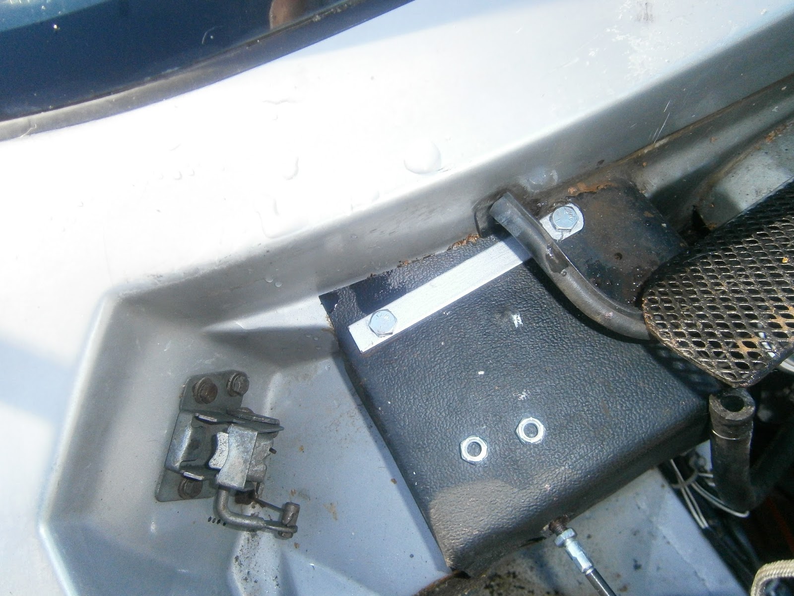
The pic below shows the switch in position on the old box in the car. Electrical contacts towards the rear of the car. Apologies for the detail here but the switch wasn't as I'd expected and so I thought I'd explain.
 |
| Brake switch in position viewed looking forwards from driver's foot well. |
Removing the old switch was a little mysterious; it looks at first as if its held on by a plastic nut at the rear which should unscrew... it isn't and it doesn't! The switch actually fits into a plastic bush which is itself a clip fit in the transverse plate of the pedal box. To remove the brake switch turn the whole switch 1/4 anticlockwise and pull it forward (ie away from the pedals). The brake switch will then slide out.
 |
| Switch removed from bush, note run of serrated ridges and smooth run adjacent. The white button at the end is the plunger which operates the actual switch; extended = on, depressed =off. |
The switch stem has two runs of serrated ridges and two smooth runs. It looks like it might be a screw thread but its not. The switch itself is the spring-operated white plunger in the stem and which protrudes from the end.
The bush is clipped into the pedal box, Depress the two clip-fit lugs and push it backwards through the box in the direction of the pedals.
 |
| Pushing the bush backwards towards the pedals after spring lugs depressed, it will push right through and come out the other side. |
The bush has two side wings that engage in slots in the box
 |
| Switch and bush removed. Wings on bush prevent it turning. |
The bush also has 2 ridges inside with a series of serrations and 2 or 4 smooth runs.
 |
| serrated ridges and smooth tracks inside the bush |
The side of the bush has two lugs that clip onto the metal of the pedal box.
 |
| Spring lugs on the side of the bush |
Push the bush into the box from the pedal side
 |
| Insert bush from the rear- ie from the pedal side and push it forward... |
Until it comes through and clips into place.
 |
| ... until it clips into place in the metal, check both clip-fit lugs are engaged. |
To fit the switch insert the stem from the front towards the pedals, aligning the ridges on the stem with the smooth runs in the bush. Push it back, it should slide easily...
 |
| Line up the ridges on the stem with the smooth tracks in the push and push switch back to desired depth. |
 |
| ... and turn it 1/4 clockwise to lock the two ridged sections together. |
... and twist to lock the two ridged sections together. This creates an interference fit that should hold the switch against the pedal pressure. When the car is recommissioned I will need to adjust this so that the switch is just depressed when the pedal is in the raised (brakes off) position. The plunger in the stem will extend as the pedal is depressed turning on the brake lights!
Bonnet release handle
Whilst the pedal box was out it was apparent that the rubber handle on the bonnet release handle had disintegrated. This is another old car part not illustrated in the parts list, later cars had a knob instead of a grip. Although you can still get the knob the grip is no longer listed. I got a replacement made by
Essentra components (search "flat finger grasp grip"). These cost only 60p... but sadly they have a minimum order of 500 and so I was lucky to get this from a friend. Fits perfectly and I glued it into place.
 |
| Bonnet release handle- new cover! |
Replacing the throttle cable
I did think about simply renewing the cable inner since the outer wasn't too bad at all. I've done this before- you just un-solder the end nipples and re-solder them to a new length of Bowden cable inner. I always think a good quality cable should have reusable brass nipples and the modern trend for moulded solder parts isn't really a good sign... sadly the nipples on my old cable turned out to consist of nothing but solder and so couldn't be reused. I decided not to chase supplies and just ordered a new cable- not cheap though!
In case you do want to take the repair your own route though I will tell you that you can get pretty much all you need from car builder solutions although you will need to look at motorcycle spares to find the nipples. The inner cable is 170 cm long between nipples (ie not including the nipples) and the outer is 142cm including the crimp-on-ferrule section (but not the screw threaded sections of the adjusters). The nipples are 5mm ball at the clevis end and 6.3mm bullet/barrel at the carb end (this was filed down to fit). The cable is 1.5mm Bowden. If you need to order the screw adjuster sections then you will need 2 of 37mm threaded screw adjusters (52mm total length including crimp/ferrule). Sadly, and despite the illustration in the catalogue listing, the new cable from SJSportscars wasn't cheap and didn't come with a clevis shackle for the pedal end and my message requesting one was never answered. All in all its just as well I kept and straightened the old one. I also found that one was attached to the new pedal box so although it should have been included I decided to leave it.
The old cable screws into the bulkhead strengthening plate just and unscrews easily by rotating the cable.
 |
| Unscrew the old cable.... |
 |
| and screw in the new- easy! |
 |
| and fitted the carb end to the throttle trunnion and cam cover steady. |
The carb end was already removed. I fitted the new cable the same way including some copper grease on the adjuster threads at both ends. Adjustment will have to wait until I have the pedal back in and the motor ready to run again. During this process the cable clip on the top of the cam belt guard simply pulled out- it doesn't seem to fit very well so I will try and fit it more firmly later.
The new box cable shackle was held to the accelerator pedal with a split pin as before. I now know that you probably will never have to remove this pin unless you misunderstand the connections, however I can think of no reason to have the thing impossible to remove so while I have the access I located and removed the split pin.
 |
| Split pin holding clevis in new pedal box cable shackle- note that the keyslot in this case faces in towards the box and away from the side of the car. |
... and replaced it with an "R" clip.
I treated any surface rust on the new box with rust converter and swapped the pedal rubbers around to get the least worn combination.
Refitting the pedal box
I was mystified by the solid metal spacers which fell out when I removed the pedal box. There were two square steel spacers (only one shown in this pic) which fit between the steering column and pedal box forward mounts. The bar however was a mystery. It doesn't appear on any parts lists, and I didn't see where it dropped from.
 |
| Mystery spacers- square ones are steel and accounted for, the bar is aluminium. |
Unlike the square spacers, the bar is made of aluminium and drilled but not threaded, the holes line up with those in the pedal box and the box itself does show an imprint of something bar-shaped having rested there for a while. I suspect therefore that this is a spacer that was fitted at the rear and on top of the box, between box and bulkhead on the inside of the car. However, it's not shown on any parts diagrams for the Excel- or even for the Elite and Eclat. It does remain possible that its a part used only on early Excels and just not shown in the parts diagrams; many early car parts aren't illustrated, although they
are usually listed in the inventory.
 |
| Position of spacer bar on top of pedal box |
Alternatively, this could be an LBPO bodge implemented to lower the box and help compensate for the bent pedal. This means I don't know whether it should be refitted or not.
I didn't get a clear answer from the forum so I phoned Lotusbits who were kind enough to look at an '83 car they happened to have in. They confirmed that the pedal box in that case fits flush up against the bulkhead. Their interpretation is that this spacer appears to be a modification probably made to improve the fit between the pedals and limbs for a shorter legged PO! This means I wont need to fit it.
Whilst I was working on the pedal box I had noticed a leak from one of the heater hoses. Removal of the pedal box also opened up access to the foot-well carpets and presented a golden opportunity to replace some of the most worn. I was therefore held up in the pedal box work in order to address these two issues which are the subject of additional blog posts. Once these were sorted I could return to the issue of the pedal box.
 |
| R clip installed in Throttle trunnion yoke clevis |
 |
| The thread on the earthing post was partially stripped. I chased it to restore and then rubbed down around to ensure good earth contact. I treated the post and surrounding area with a smear of dielectric grease. |
Before fitting the box, I refitted the clutch MC while access was relatively simple. After that, refitting the pedal box was quite a struggle- it involves trying to push and pull in positions where its not possible to exert much force. Its also virtually impossible to see bolts and screw holes and much of the work is conducted inside my LDDV so I couldn't focus on them anyway! It probably would be better if I didn't need glasses! The other problem is that space is limited. You can bend and strain as much as you like, but you can't shorten the distance between shoulder and elbow or elbow and wrist!This job would be much easier if I were shorter but at 6.1" with long levers its hard to fit myself into the foot well. Undoubtedly this job really needs two (preferably younger and smaller) people- one to work in the engine bay and the other inside the car. This would probably eliminate much of the wriggling in and out that I was obliged to do, and bolting up would be easier with someone to hold bolt heads on the outside! Its all made harder by the fact that the steering column spacers aren't captive and keep falling out. I taped them in with masking tape so that I could orient the box without losing them.
 |
| Spacers nuts taped into position. |
When I had removed the box, I hadn't been able to remove the relay terminal block until I had tilted the box to the side. This meant that the wires were strained, and to avoid that in refitting decided to fit them after the box. I slipped the box side lugs over the steering column and pushed the box forwards against the bulkhead. This was not easy! I had to hold up cables and branches of the loom to make sure that nothing was trapped as the box was offered up. The speedometer cable was also withdrawn and kept out of the way. I will try to route this around the box towards the speedometer after the box is fitted. It involves quite a lot of force and I hope hasn't strained the wiring too much. Once the pedal box was approximately right I could hold the front in place by loosely fitting the two large bolts into the captive spacers to hold it at the front at least.
I could then fit the relay terminal block through the instrument panel hole using a flexible screwdriver- not easy but at least possible!
 |
| Flexible screwdriver to fasten relay block mounting screws. |
I did find that the holes in the new pedal box weren't quite the same size as the old- consequently the self tappers were too small and I had to replace them with wider screws. If I were doing this again I would definitely check the screws for size and ease of threading before inserting the box! I also used this access to check that the earth wire from the relay mounting was routed towards the earthing post with sufficient slack.
 |
| Relay mounting screws accessed through instrument panel and screwed in. |
I could then push the pedal box forward towards the bulkhead and up against the car body. This was very difficult because of wire, cable, heater ducts. Take car that the clutch MC push rod is well positioned in relation to the clutch operating lever extension from the pedal box.
To my surprise I found that there was a large gap between the top of the box and the car body under the the two top fixing bolts- this meant that I had to fit the aluminium spacer after all; even though it would seem that this isn't a real Lotus part. Without it the two top bolts would distort the box as they are tightened. Fitting it was a real pig as the box was already in place. If I had known that it would be needed I would have taped it in place as I did the two steering column mountings. As it was, I had to loosen the front bolts and insert the spacer from the side. I was able to position it and hold it in place with two screwdrivers penetrating from above.
 |
| Spacer bar held in place from above with two penetrating screwdrivers. |
I raised the rear of the box through the servo push rod hole until the servo mounting holes coincided and then held it there temporarily by inserting two loose bolts.
 |
| Box is sitting lower at the bulkhead- the servo access cutout in the box doesn't quite coincide with that in the bulkhead (too low, crescent of box visible inside top of hole, and the screw holes aren't lined up. |
 |
| Raise the pedal bow by pushing the box up through the servo push rod hole until the bolt holes coincide and then fix it in position using two loose bolts. |
As the box was now lined up I could remove the screwdrivers one at a time and replace them with the two mounting bolts.
 |
| Two mounting bolts penetrate from above through car body, spacer bar and pedal box beneath. |
More gymnastics saw the two mounting nuts added from inside the car (see removal for the arrangement of extension rods) and the box was then tightened up against the top of the firewall bulkhead. The two loose bolts could then be removed- the box dropped a little but I could adjust its height by tightening or loosening the L and R bolts from the inside until the servo mounting holes lined up. This they never did perfectly, but well enough for the servo to be finagled into position (you will need to remove the brake master cylinder to make sufficient room). Make sure that you pay attention to the position of the push rod clevis fork as you push the servo body backwards- the clevis yoke has to slip over the shaft of the brake pedal- again it helps if there are two of you! Once the servo was in place I could fasten its retaining nuts from inside the car and refit the brake master cylinder.
The job's not yet finished, but at this stage it is already apparent that the new box has completely solved the alignment problem between clutch m/c push-rod and clutch pedal extension operating lever.
 |
| Clutch MC push rod now in line with the operating lever (pedal extension) which is visible at the top of the picture. This is not yet connected but will now fit easily and push in a straight line! |
At this stage I was interrupted by nightfall- I had needed app 8 hours to refit the box- largely because I kept finding things I should have done earlier and so had to keep backtracking. At this stage I have still to connect the two m/c push-rods and throttle cable, adjust everything, tighten the earth post connection and reconnect the speedometer cable before refitting the dashpod. However, this post is already quite long enough, and so in the hope that those tasks will be straightforward, I thought it a good idea to publish the position so far. I will add more notes if anything significant should arise.