The DHLA45 is probably the pinnacle of carburettor development: the last flowering of that black art before carbs were pretty much universally abandoned for injection systems. As such these are devilishly complex carburettors! I do know why this car was laid up- and it wasn't due to carburettor failure. This of course doesn't mean that the carbs haven't been messed about in the intervening years or simply become gummed up with crystalline deposits from long vanished fuel. Anyway I had intended to leave them well alone but sadly this proved not to be possible. Firstly the nuts on one carb were only hand tight- I therefore detect the malevolent lurking presence of the LBPO- and there is no telling what he might have done! Secondly, the carbs had been left exposed to the air with no airbox and the bonnet open for some time before I got the car. There is a lot of grit and general muck blown into them. It doesn't look like I can avoid a clean, strip and rebuild but hey- its all a learning curve! Luckily I found Des Hammill's excellent book on Dellorto and Weber carburettors which is an excellent guide and has increased my confidence to the point where I just feel able to tackle something!
The first problem was getting the carbs off the manifold. I gave the lot a good clean with paraffin and then carb cleaner and set about removing the carbs- each is mounted to the manifold by 4 bolts which pass through MISAB double rubber washers sandwiched between cup washers. The anti-vibration mounting for the carbs to the inlet manifold is completed by rubber mounted metal rings also made by MISAB in Sweden.
 |
| Carb mounting bolt- shock absorbing mounts consist of: cup washer/double rubber washer/cup washer |
The carbs are linked so that their throttles operate together. This is achieved via a peculiar sliding link so that they can be disconnected without affecting the setting. However they can't slide apart until they've been moved forwards and off the studs. What this means is that its not possible to remove just one carb- you have to dismount the pair and then split them. No real problem as I do need to clean both- but I will dismantle them one at a time!
 |
| Sliding mount joint between the throttle levers. |
 |
| Sliding mount from 90 degrees- note the spring loaded adjuster screw pressing down on the spring loaded pad. Between then is the link lever from the next carb. |
 |
| Removing the carbs and separating the slip link |
 |
| Sliding joint separated-note tab on throttle lever lhs carb that slips between the two spring loaded screws on the rhs carb. |
 |
| This is the cleaned carb that the LBPO had been messing with. |
I unscrewed the two screws holding the top plate on to expose and remove the gasket beneath.
 |
| Gasket below top cover |
 |
| Removed to expose jets |
This exposed the two main jet/emulsifier tubes (larger) and pilot jets and emulsifiers (smaller). These 4 jets simply unscrew- the pilot jet being a little stiffer as it has an O ring on it. Both types of jet are composite units and just pull apart.
 |
| Main jet emulsifier unit |
There was some trace of dirt on the jets but I've seen worse...
 |
| slight amount of dirt on main jet |
 |
| Removing the pilot jet |
7
 |
| Slightly more dirt on these. |
Surprisingly the remaining screws in the carb were all very tight- which suggests the LBPO gave up fairly early in his bodging mission of destruction. I loosened them with an offset screwdriver.
 |
| Loosening the cover screw on the progression holes |
Exposing the progression holes also found a little more sediment- there was a surprisingly large number of these holes; I was only expecting 4! The black plugs above the progression holes are the blanking plugs that keep grit out of the mixture screw threads.
The next step was to remove the venturi and choke tubes which sit in the carb throat. The venturi is farthest from the throttle butterfly- in my case it was a bit dirty.
 |
| Venturi- some obvious dirt in there and some sticky gum cementing them in. This is the airbox side of the carb and i had expected 4 studs per carb for attachment. Strangely I have only 2 and the vacant hole is visible here. This hole hasn't even been tapped so I dont think I have a stud missing. Maybe a nut and bolt? |
 |
| Venturi looking through the venturi and choke tube towards throttle butterfly, single support for the central venturi. |
The venturi is held in with a stud and lock nut on the side of the carb- I removed these.
 |
| Venturi locknut visible below acceleration pump. |
The venturi and choke are both tight fits in the carb body. To remove the venturi you need to warm the carb to loosen this grip and then tap the venturi out away from the butterfly using a wooden drift inserted through the butterfly which is opened to allow this. I used a dowel drift on the supporting arm visible in the venturi illustrated above. A few taps saw the dowel split but the venturi shifted
 |
| Dowel through the butterfly and onto the venturi support strut- hold the carb and tap firmly with the hammer. |
 |
| Venturi emerging |
Given that the venturi was tight I had expected the choke to be tighter- apparently it can be a real pig. Luckily the choke just fell out once the venturi was free.
 |
| Choke dropped out with the venturi |
 |
| Venturi is rough and pitted- will need smoothing before refitting. |
The other side behaved in the same way. I stored them separately, marked as to which side of the carb they had come from. I'm not sure this is essential but seemed a sensible precaution.
I then removed the acceleration jet (brass screw located behind the progression hole cover).
 |
| Removing the acceleration jet. |
The jet and cover screw are linked and do not obviously separate for cleaning. They are probably just a firm pull but I don't want to break anything.The lower part is loose in the upper so I did the best I could to make sure that the holes were clear and carb cleaner squirted through.
 |
| Cover screw with acceleration jet inserted |
I removed the top cover by unscrewing the 4 screws; 1 of which bears the ID tag for the carb.
 |
| removing the top cover |
I could then tap the cover loose and lift it upwards- note it has to go up vertically a couple of mm to clear the choke tower
 |
| Raising the top cover- choke tower has to clear the cylindrical projection below- this can be tight and needed a tap to free it in my case. |
 |
| Float chamber cover removed |
As the top was lifted the floats became visible beneath. These have to be removed to swap the gasket below
 |
| Floats hanging beneath chamber cover, note black gasket above floats- can't be changed without removing the floats. |
To remove the floats you need to tap out the pin but from the solid support side-
towards and through the split support. Reinstall the same way as to tap on the split support risks breaking it!
 |
| Using a small pin punch to tap out the float pin |
Once the pin was out the floats came away with the needle valve inserted between the forks as shown here.
 |
| Needle valve fixed to float hinge |
I set the float aside and then returned to the float chamber cover. This is shown below; the fuel inlet is at the top (large brass nut) which then discharges vertically through the smaller brass needle valve fitting which includes an integral filter. This system seems to differ from those shown in the Hammill book where fuel intakes are banjo unions with a large filter inside the cover- I had no such filter. I removed the gasket from the detached chamber top
 |
| Peeling the gasket back from the underside of the float chamber cover. Fuel inlet at top centre- fuel outlet to float chamber (needle valve body) is the brass fitting below |
|
| Detached float chamber cover from above-choke tower centre and fuel inlet beneath my thumb. |
The fuel inlet simply unscrews from the cover- there is a bonded washer (Dowty washer) beneath but no filter inside in my case!
 |
| unscrewing the fuel inlet |
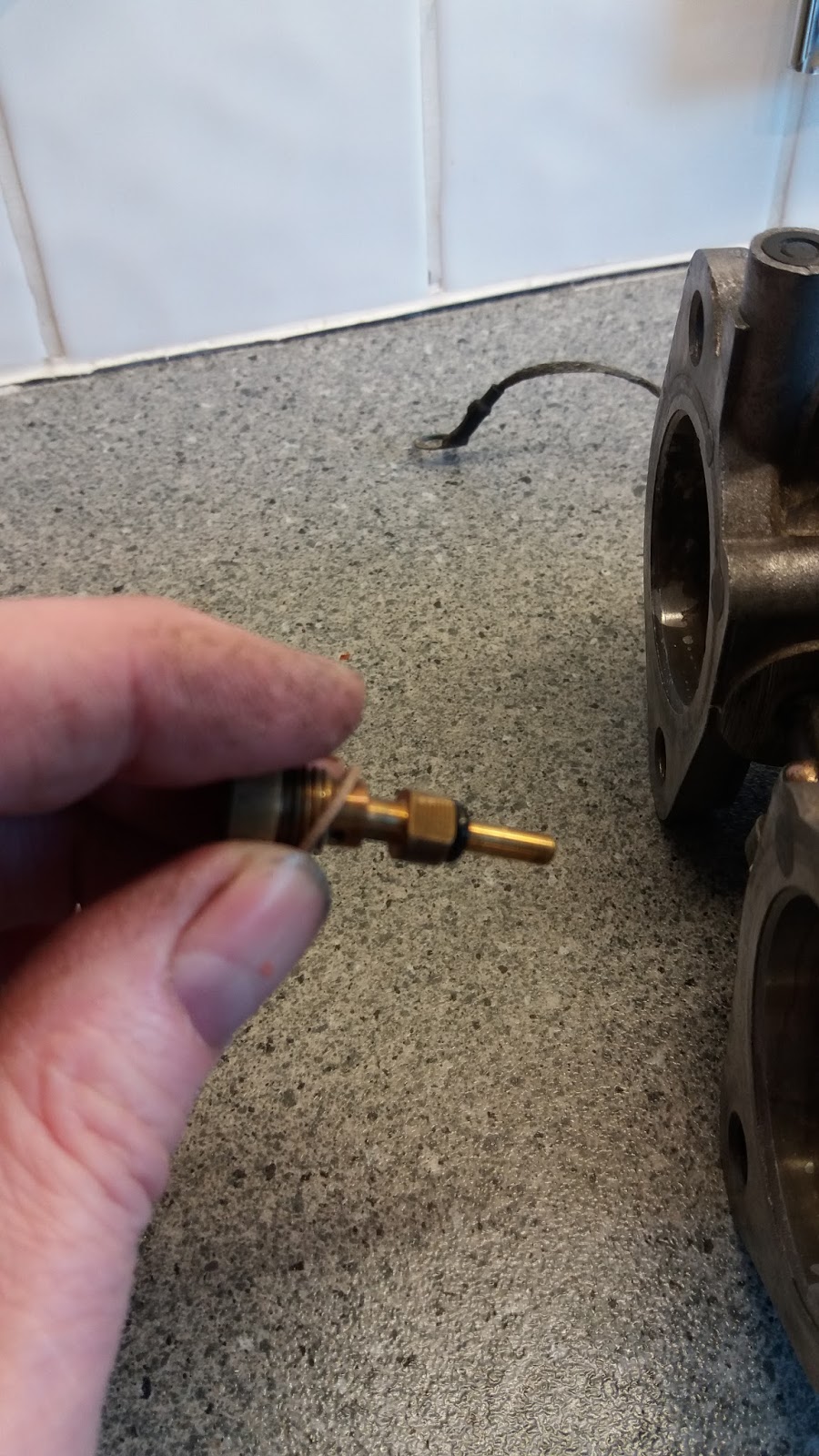
The fuel outlet/needle valve body also unscrews from the cover and this does have a small filter inserted in one end. It was fairly dirty but not by any means clogged.
 |
| Removing the fuel to float chamber outlet from the cover |
The filter itself was in good condition- which is just as well as the rebuild kits from Eurocarb contain only the larger banjo type filter.
 |
| Filter in needle valve body- aluminium washer beneath. |
I could then turn my attention to the float chamber; This contained a fairly significant amount of dirt which I flushed out and blasted through all the openings with carb cleaner.
 |
| Muck in the float chamber |
The float chamber has three brass screws at its end, these consist of the choke emulsifier tube and the acceleration pump metering weights under their covers on either side of it. Outside the float chamber and adjacent to the two progression hole covers is another pair of slotted brass screws which are called the vacuum blanking screws. I have no idea what these do but I suspect they simply close off a moulding or machining channel that is not needed.
 |
| Choke tower (top) Choke emulsifier tube (brass centre) and the two acceleration pump metering weights (under the screws each side of the choke emulsifier). Vacuum blanking screws above the metering covers outside the chamber and beside the progression hole caovering screws. |
The choke emulsifier just unscrews and could be cleaned with the carb cleaner
The metering system screw covers were removed and the weight and ball removed- the balls were gummed in the bottom of the bore and so this probably needed doing!
Turning the carb upside down caused the long weight to drop out but the balls needed to be freed with spray cleaner.
 |
| Acceleration pump metering system- ball bearing, bar weight and cover screw. The ball goes at the bottom of the bore with the weight on top. |
I then removed the two external vacuum blanking brass screws
... and this completed the strip down of that side of the carb.
 |
| Top of carb-stripped! |
I could then turn the carb over and dismantle the main well cover. This is in two parts- the centre part is the acceleration pump and this needs to be removed first- 4 screws only.
 |
| Unscrewing the acceleration pump 4 screws |
The pump is operated by a spring loaded lever- the length of this seems critical and I was warned not to touch it so I just folded the cover out of the way once it was released.
 |
| Cover folds back to reveal pump diaphragm.Some muck on the pump cover and rather more on the diaphragm. |
I could peel the diaphragm back releasing its spring.- again a little more muck underneath the diaphragm. Once again I cleaned this out and blasted though the various bore holes with carb cleaner.
... peel back the pump diaphragm...
 |
| Pump diaphragm removed |
I could then unscrew the outer 4 screws retaining the bottom well cover and ...
|
|
Unscrew the 4 bottom well cover screws
|
... and pull off the bottom well cover and its internal gasket
... a lot of muck inside the cover- this is the lowest part of the carb and I guess is intended to collect this sediment. It will also collect any water in the fuel so there are also signs of corrosion here which I will rub smooth before refitting.
 |
| Sediment in bottom well-cover- this was washed off with carb cleaner. |
The large brass fitting in the well cover is the acceleration pump non-return valve- a hollow brass tube with a captive ball bearing. This was unscrewed and cleaned thoroughly with carb cleaner.
 |
| Acceleration pump non return valve |
I would usually immerse the carb in sonication fluid- this isn't recommended in the book mainly because it might dislodge more muck into the passages. However I haven't found that to be a real problem with other carbs I have cleaned. None the less there is still a problem with this approach, as unlike other carbs I have worked on, this one contains 4 ball- bearing races. High temperature sonication would probably remove all grease from these bearings! I would change them as they aren't that expensive but they cannot be changed without removing the butterflies and spindles- and this is a major job since any misalignment on refit could make the carbs useless. Accordingly I have no intention of doing this.
As a compromise I immersed the carb but only to a level below the bearings. for sonication. I brushed the top section to clean it. I will remove the oil seals, clean and regrease the bearings (without removing them) when I rebuild the carbs.
 |
| Cleaning the carb bodies. Bearing clear of water. |
I will work my way through cleaning the other components and finally blast them through with compressed air. In the meantime I have ordered a rebuild kit (170 needle size) from Eurocarb.
There are only two parts I haven't actually removed. The first are the mixture adjusting screws in their turrets and covered with tamper proof plugs. To be frank I'm not sure how to remove these (drill and tap then pull the screw?) but I have checked that the screws aren't blocked and are open to gas movement by squirting carb cleaner through. I have ordered some new plugs so I may return to this point later.
The second part is the choke system. Hammill isn't very helpful with this part as he states it hardly ever goes wrong and so doesn't describe it- however its probably not a good idea to immerse this either so I cleaned it as before, without submerging the choke tower, and cleaned everything through with penetrating oil afterwards to remove any water. that might have got in.
To be frank- although I found a lot of muck, I have seen worse (!) and I doubt that this level of contamination would have stopped the carbs from working completely. However they might have been unreliable and so overall this is probably a job that needed doing. Sadly stripping, cleaning and rebuilding is relatively easy- its the multitude of adjustments needed as a consequence that might defeat me! The second carb will be treated as the first and rebuilding is expected to be (as they say) a reversal of disassembly! I will post another blog on that as a record.
NOTE
 |
| top of carb 2 to orient the tag and cable guide fittings |
 |
| cable guide indicated. |
I hadn't expected to be adding anything more to this particular blog but (as might have been predicted), carb 2 turned out to be rather worse than carb 1. There was a lot more dirt on the needle valve filter and sticky deposits throughout.
 |
| gummed up valve |
Removing the Venturis was particularly hard with the wooden drifts splitting rather than shifting them- even after warming! I found that a polypropylene rod drift worked much better, didn't mark the Venturi but allowed me to exert enough force that they finally gave up. The chokes fell out as before which was a pleasant surprise- I had expected problems.
 |
| Muck in Venturis |
One acceleration pump metering ball was stuck immovably in its hole and had to be physically dislodged, the acceleration pump non return valve was also stuck fast.
 |
| Non return valve |
The acceleration pump jets were also stuck and didn't move freely in their cap screw/holder although they weren't blocked. There was a lot more dirt, and possibly even corrosion on the main jet assemblies.
 |
| Corrosion and dirt on main jet. |
Nothing appeared to be blocked though. I cleaned everything up in the sonicator as before and checked that all the channels were open. In this case- given the levels of dirt, I did remove the tamper plugs and check the air control screws were clear- in act they were fine but it was worth checking. In my case both screws need to be bottomed out in their threads and then screwed back 2 3/4 turns.
 |
| sediment inside bottom well. |
Cleaning the carbs was started partially as a displacement activity because I am more than a little concerned about what might happen when I try to start the wretched thing- but if it was a displacement activity then it is one that has proved valuable. This was clearly a job that needed doing and so I feel vindicated in tackling it before attempting to restart the motor.