Caliper Refurb
Removing the piston on the RHS caliper proved to be a real problem. In the end I was able to remove it by gripping it in a mole wrench and hammering the wrench outwards. This scratched the top on the piston although as this is not a sealing part it shouldn't matter. However on examination I did see some scoring on the piston itself and so decided to renew to be on the safe side. However I wasn't impressed with this approach. The left hand piston was also stuck in place. I hadn't liked the mole grips approach so I made this:
Bad pic sorry, but I took a brake union nut, drilled it through at 5.5 mm and tapped it to M6. I could then screw a grease gun nipple into it and screw the part into the caliper brake pipe socket.
I made sure that the caliper was full of fluid and then pumped with a grease gun- after a few pulls the piston eased out. This was a really successful method but you must remember to clean out the fluid ways in the caliper as they will be packed with grease. It also does lead to a very messy caliper. I understand that you can put oil or fluid into the grease gun which might keep the mess down, but then again the possibilities for rampant oil spray are legion!
Both calipers were cleaned by sonication and then soaked in DeoxC overnight to remove most of the rust. I then dried them, wire brushed any remaining cruddy rust deposits and treated with Jenolite before spraying. Brake calipers can get very hot and I didn't want to buy any dedicated caliper paint so I used alloy effect UHT engine paint. This should cope with the heat and I think it looks good. I didn't want to use anything too gaudy like a red as it might seem to give this poor car delusions of grandeur. The downside though, this type of paint will strip very easily in brake fluid!
 |
| Removed and cleaned brake pipe bracket |
 |
| Seal in groove below top of cylinder . Some marking inside cylinder itself. I was able to clean all the grooves and smooth the inside of the cylinder using a soft brass brush in a Dremmel. |
 |
| Existing seal removed |
The pistons seal against a ring seal placed just below the top of the cylinder. This could be removed easily. I had expected it to have a defined "up" and "down" but it appears to be flat. I will check with Bigg Red before I fit the replacement. The inside of the cylinder is looking a little rough after the derust treatment, but this isn't a sealing surface so I don't expect it to cause a problem.
 |
| Caliper cleaned and painted. Grooves for boot and seal cleaned and polished with the Dremmel |
 |
| Bigg Red seal kit- new seal |
 |
| Lube with fresh brake fluid and insert into caliper groove. This seal doesn't have a defined up or down |
 |
| I like to use this stuff on the exposed parts of the piston (i.e. above the seal) its rubber friendly and stops rusting dead. |
 |
| Insert new piston (lubed with fluid) and smear some corrosion block grease around the top before... |
 |
| Easing in the top boot and retaining it with the circlip. |
 |
| I am slightly concerned that I can see the circlip so I may refit this as I think its supposed to engage inside the external ring of the boot and so be hidden when fitted.. |
The sliding bushes and seals were also replaced
 |
| Withdraw the pivot lock bolt sleeve |
 |
| Apply corrosion block to the sleeve outside, check for new rubber seal and.. |
 |
| Pull out the old tube seal and insert the new before... |
 |
| ... finally re-inserting the lubed sleeve. |
The pivot bolt sleeve was replaced in the same way, although it needed to be tapped off with a punch
 |
| Corrosion block grease inside sleeve. |
 |
| Fit the new rubber boot finger tight and then slip a 22mm socket over it so as not to catch the rubber concertina at all. |
 |
| Socket in position, all rubber out of the way... tap home to seat the new boot. |
 |
| Finished caliper underside... |
 |
| ... and from above, nipple still to go back, kit also included new nipple caps. |
This does look a whole hill better than I had found them, although I still need to work out how to fit new pads- there was a multiplicity of clips and heaven-only knows how they go back!
HUBS
I was very pleased with the effect of DeoxC de-ruster on the disc/hub unit, this was left to soak overnight and then washed with detergent
 |
| disc/hub derusted |
 |
| and another view |
 |
| The brake back plate was rusty- so it was cleaned with brake cleaner to degrease and then wire brushed before receiving one coat of Aldi metal protection paint |
 |
| Much better. |
The hub could then be refitted although refitting the caliper will have to wait for the repair kit to come from Bigg Red- I have ordered a kit for both calipers (BRK203822) and also two new pistons (BRP233819) - so there should be no problem with these working now. In the meantime I am soaking both caliper and frame in de-ruster before I repaint these.
Replacing the rear brake pads
The fitting of the rear pads is a bit of a nightmare. To be frank I struggled. Please consult your manual and do not necessarily accept what I report here as correct! I have put the thing back together but its not yet tested. I will try to amend this blog when I know that this description is right (... or wrong!).
The manual recommends fitting the clips one at a time to each caliper in turn. This is probably a very good idea provided that the clips all stay in position as the brackets are removed and the pads taken out of them- in my case several did drop out. The drawings in the manual are confusing and they don't show how the pads and clips fit into the torque bracket. I tried to fit them using the pivot pin as a reference point for both left and right calipers and following the drawings in the manual- however its a constant battle to try and remember left and right, and front and rear and switching from "as drawn" to"mirror image"!
NOTE when the new pads arrive they are packed separately for each side with the appropriate clips. My pads were genuine Lotus parts (NOS), but the box was partially unpacked and the clips were muddled up. This was a nightmare;
The important point is that many of these clips are actually handed- they fit to either left or right sides, not necessarily both. It is not clear which one you need for which side from the diagrams.
The following are my conclusions based on performing this exercise several times until it seems right. I apologise for making heavy weather of what is basically very simple but it took me ages to work it out and trying to describe it in words is quite tricky. Don't take it as Gospel.
The clips are of four types and 3 types have a flat region that either fits into a recess in the pad or lines a recess into which lugs on the pad will fit. I lubed these regions lightly with silicone grease when fitting the pads so that they can slide towards and away from the disc smoothly.
Outer pad fitting:
The first type are front (outer) pad mounting clips (which I am calling Vee clips). These are supplied as two matched pairs; an upper and a lower clip which are mirror images of each other. As long as you have a matched pair you can fit them to either side.
 |
| This is a pair of front pad (outer pad) mounting clips for LH torque bracket |
The flat pad-like regions above fit over the torque bracket tongues to locate into the recesses in the side of this pad. The Vee sections are sprung down to engage with the pad recesses as well and then act to spring the pad against the bracket, holding it in position. This causes the Vee regions of the clip to spring away from the bracket. The square lugs visible at the top in this pic clip into the the outside slot in the torque bracket to retain the clips. The longer projecting tangs on the top of the clips (in this orientation) face away from the pads.
 |
| Outer pad in clips from above. Note the square spring sections clipped into the recess at the front of the bracket. |
 |
| View from outside, the folded clips have risen away from and below the bracket. They now spring the pad down against the bracket to hold it in place. Note anti-squeal shim |
 |
| View when fitted into caliper. |
Inner Pad
This is retained by three clips- all different! Two fit the sides of the pad (one each side) and I am calling these the simple and the complex clips. In addition there is a long wavy clip that fits beneath the pad.
The simple clip is interchangeable between the sides, its not handed and fits either side. It clips in to line a recess in the bracket next to the caliper pivot mount, the triangular sections gripping over the sides to hold it in place. Make sure the short side matches the shorter side of the bracket recess. The function of this clip is to provide a strong stop against which the pad is forced by the complex spring clip on the other side.

The complex clip is handed and you will need to fit the correct one to each side. It fits nearest the pivot locking bolt, the springloop section pointing away from the pads and towards the caliper. The lugs visible in this pic pointing upwards will line a recess in the torque bracket in which projections on the pad will slide. Once again, make sure that the large and small lugs match the profile of the recess. Clips at the back (bottom in the pic) grip the bracket to hold the clip in place. The spring section is compressed beside the pad as it is inserted. This provides spring pressure forcing the pad up against the strong stop (simple) clip on the other side.
 |
| This is the complex clip for the inner pad (lower position). The loop spring part fits away for the pad behind the bracket and caliper. In this view the pad would fit vertically and the spring below my finger would press on pad inside the mounting groove to push it up against the hard stop clip at the other end. |
 |
| Inner pad slipped into clips. Note "simple" clip nearest pivot mount, complex clip nearest pivot lock bolt and projecting up (in this pic) towards where the caliper will be. |
View of inner pad from the back of the bracket (I.E. from inside the car). Note the lugs on the pad engage the lined recesses in the bracket. The complex clip is pointing up towards the camera. The wavy clip is inserted at the bottom over the crescent section of the bracket with the square mounting clips pointing towards the caliper position..
The wavy clip fits over the crescent of the torque bracket under the pad, springing the pad upwards (in this pic) to hold it against the recesses in the bracket. Make sure that the piston is fully retracted and offer up the caliper, securing it with the lock bolt. I put a smear of copper grease between the caliper prongs and anti-squeal shim.
 |
| Caliper fitted |
The whole assembly can then be fitted to the disc and if everything is assembled correctly the pads should stay in place as you flap it about to try and locate the two bolt holes. However make sure that the short metal pipe on the rear isnt folded around as this will prevent the caliper from seating properly
 |
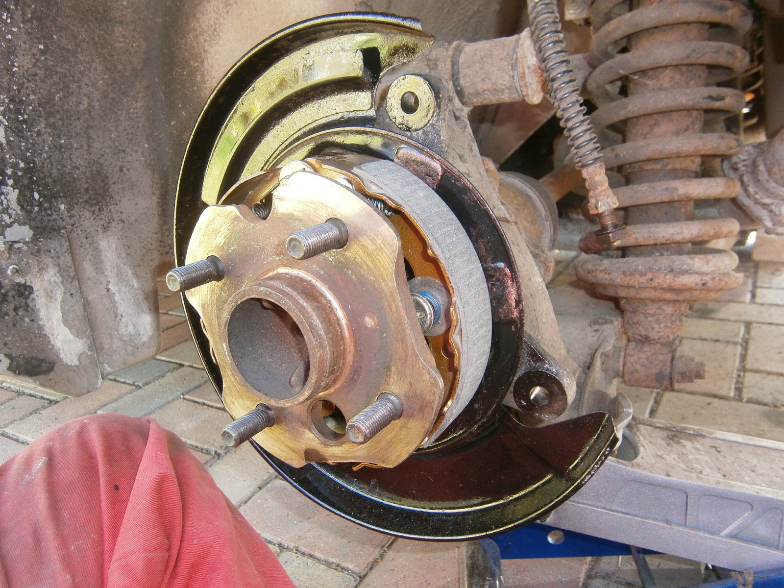
| Disc fitted and ready, handbrake shoes inside so good to go! |
Well it took a few goes but eventually I go everything refitted
 |
| Caliper fitted to disc. |
 |
| Tightening the metal brake pipe at the rear of the caliper. Note new braided hose in position. |
Of course the short metal brake pipe on the back of the caliper can't really be tightened until everything is fitted and aligned. At this point it becomes impossible to tighten it because access is blocked in every direction by caliper pipe or suspension parts! I found the answer was a 3/8 drive crows foot spanner slipped in from above. Very satisfying that, as I bought those spanners years ago at an auto-jumble and this is the first time I've actually needed them!
I had already changed the flexible pipe for a new braided pipe set from Black Diamond. I have to say that Unscrewing the inner flexible/fixed pipe union was dreadful! Access limits mean that only short spanners will fit and awkward access means that its virtually impossible to put enough force on them to turn the nuts. Some three hours later it finally shifted. Best I can recommend is to unscrew the fixed pipe union and pull it back away from the hose until you can slip a 15mm half-moon ring spanner over the hose union nut, then use a 17 mm stubby on the other side. To prevent this trouble in future I used copper anti sieze grease on the threads when this was tightened.