Search for tasks- type in keywords

Tuesday 23 August 2016

Lotus 912 motor: Machining the crank, transporting the motor

Getting the crank modified.

As far as I can tell the main problems are twofold-
Firstly, the splines of the gearbox shaft (or perhaps the conical shaping beyond them) fouled on the front of the flywheel because this isn't drilled deeply enough.
Secondly, the spigot bearing isn't recessed far enough into the crankshaft to allow the shaft to slide in fully.  I'm sure there is a wealth of Freudian comments but sadly all escape me at present. The sum total of my investigations is shown below:

This is the crank boss as it is and my drawing below


This is the central crank boss as present on the automatic motor. Central opening is narrow and shallow with the spigot bearing recessed only 3 mm from the flange edge. This is achieved by limiting the accurate reaming of the bearing hole to 18.5 mm depth.

This is what I need- the central boring is enlarged to clear the splines on the gearbox shaft (28.5 mm diameter). I have suggested boring to 32mm to provide enough clearance and deepening this bore to 9 mm. I've drawn this as a milled out flat bottomed recess but a conical section is also fine as long as its deep enough. At the same time the spigot bearing hole is not enlarged, but reamed to an additional 7 mm depth (25 mm) to accept the bearing in a lower position.
 The spigot bearing measures 21.002 mm in diameter in a digital micrometer, so the central hole is presumably slightly less than this. The best I can gauge from calipers is 20.82 mm. However I lack the tools to measure this internal dimension accurately. I will leave a spare bearing with the engineers so they can test the fit.
I am also a bit mystified about the depth of the spigot/pilot bearing hole. My investigations using a wide drill bit suggested the the manual motor is drilled some 3mm deeper. However measuring the depth with calipers finds the same depth in both. I think this must indicate the drillings have different end profiles and the auto motor tapers more sharply. I will try to get it deepened by 3mm over an 18mm diameter which should accept the gearbox shaft and give enough side clearance for the machining to avoid damaging the section already reamed. Note: this is not shown on the drawing!
In the meantime I removed the alternator and PAS pump and associated belts to help access. I did also remove the cambelt but the company didn't want to risk machining with no belt in case the crank rotated a little so I will refit that today- seems a sensible point!

The next big problem is how to move the motor. I collected it on my trailer... This is a single motorcycle trailer but I made a detachable flat bed out of plywood a long time ago to accommodate non-motorcycle loads. This was fine for collecting the motor- BUT at that time the head was off. Now its connected the unit is heavier and very much top heavy so its unstable. I must get it fixed in position.

Well that was a real nightmare. I don't necessarily recommend this but if you are faced with the same problem this at least is one solution! Eventually I opted to fix a 10x5cm wooden frame around the sump. The front section was cut to 9cms height so that it could pass under and support the smaller sump depth at the front of the motor which hung over the frame. I also cut a short section out of the RHS frame to accommodate a projection in the cases. This frame was fixed to the wooden bed of the trailer to prevent to/fro and fore/aft sliding; the whole being positioned along the line of the trailer axle to avoid placing excessive vertical forces on the tow link. Also it makes the trailer much easier to move when the motor's weight need only be pivoted (not lifted) when raising the front to attach/detach the tow ball.

The motor was  top heavy owing to the inclined head and tended to fall onto its exhaust side even when the sump is square on the trailer bed. To oppose this I fitted 4 props to support the motor upright. The first two were 37 cm struts of 8x5cm timber fitted with a square-cut end under the exhaust manifold. Their other ends were cut at 45 degrees which allowed them to sit flat on the bed. I fixed another cross member behind these for added strength. I cut another two struts from 6x4 cm. These were 40 cm long and their square-cut ends were fitted above the exhaust manifold supporting the head and screwed at their lower ends onto another cross baton of 8x5 fixed to the bed. Their lower ends being cut at cut at 45 degrees to  sit flat on this cross brace. When these props were screwed into place they supported the motor to stop it toppling, but as they were fitted into the concave side (exhaust side) of the inclined motor, they had to be unscrewed before the motor was removable from the trailer.
Making the sump frame- 10cm timber. Note slot cut to accommodate projection in sump at  motor RHS. Note the front of the motor overhangs the frame and sits in the 1cm cutout.

Front timber, 1cm cut off the top giving a 9cm height to pass below and support the front of the sump 

View of both sets of props, the two forward props fit against the block below the inlet manifold and are braced at their bases. The upper pair of props fit against the head above the exhaust manifold and are screwed to a cross batten at their lower ends. Later I put two cross pieces to help steady these in the lateral direction.


Side view (rear of motor) showing sump cage rear and RHS. Both sets of props visible

Both pairs of props in close up, upper pair yet to be screwed down.

Overview- note props yet to be screwed down.

Once I was happy with the security I removed these steadies and took the motor out of the trailer to fit it properly. I plugged all the open holes and covered the top of the motor with plastic sheeting. I then covered the cradle with a tarp before lowering the motor in on top. The tarp was then wrapped around the motor (inc the strops which were left in position) and secured with duck tape.
Wrapped motor in cradle- note props fitted outside the tarp.  Steadies added to cross-link the two upper props.


Ready to go

Finally the motor was tied down with ratchet straps. This arrangement was very secure and withstood the journey well. The coverings also protected it from torrential rain on the way.

This is the machine Myanengineering will use to work on the motor- Its from the aero industry and can manoeuvre loads of up to 3 tonnes in order to position them correctly for machining. Very impressive; it should cope easily with my motor.

Machining in progress.


Well its been 3 weeks... but I heard today the motor is finished. I will get down to collect it next Tuesday so wish me luck!!

Motor as received ... the face has been opened out and if you zoom in the new reaming at the base of the spigot bearing socket is clear.


And for comparison... as sent!
Well the end has certainly been modified- there should be enough room now for the gearbox spigot. I am slightly concerned that the spigot bearing is no longer such a tight interference fit in the crank end so I will use a little Loctite retaining compound to help fix it in place.

Tuesday 16 August 2016

How did this happen?

 I have been asked a few times how I ended up with the wrong motor. Well its a cautionary tale so even though this is nothing to do with fixing an Excel I will explain. I also welcome the opportunity to get this off my chest!

I'm sure you've guessed it was an Ebay sale. Advertised by Paignton-based Ebay user Mark041261 as Lotus Excel Esprit Austin Healey Engine #331297413737 . The description (now cleared from Ebay) went on to describe that the motor was in good condition and my emails to the seller confirmed that this was the case: The head had been removed to check and he confirmed that it had never had a cambelt failure and was derived from a rear-ended Excel, the owner of which was known to him through the owners' forum.  It had red cam covers but these were badly worn and looked like a DIY repaint job, he confirmed that this was a LC motor as I had expected. The important point here is that although it wasn't given in the ad, I  asked for the motor number and received a genuine Lotus engine number (D91282730335) identifying the motor as no 30335; a manual 912 from 1982, the first year of the Excel build.  The motor was near Paignton, Devon (a couple of hundred miles away), and there was an option on a leather interior from a later Excel too. Price was OK so I journeyed to collect the lot.... and I took the motor, interior and a load of mechanical/electrical parts too. It was a big collection and filled the trailer and the van. The motor looked like the one in the ad... certainly the faded red cam covers were the same- but of course these weren't attached to the motor at the time. However - and this is the real point... I didn't have the motor number with me as that was in an email not the ad!!! (Idiot!). I did check from the number that this was indeed a 1982 motor, and a 912 but I am afraid the significance of the second character ("T") escaped me. Well  Mark041261 seemed like a genuine guy with a real (although past) interest in Lotuses. We got on well and  frankly it didn't occur to me to doubt its authenticity.  Well that's history and caveat emptor clearly applies. The motor I received was actually no DT912820720365.... a much less valuable Eclat automatic motor.

Although this took place some 2 years ago I did contact Mark 041261. I wasn't looking for compensation at this remove, but I wanted him to know that I wasn't happy. After a brief exchange this ended with:

Ok, you've have had your say, so where do you think I got the numbers from, the Lottery? This is my last response, it's obvious you are looking for someone to blame for your problem.

Well frankly yes I am ... and I've found him; I blame Mark041261! Had this motor been correctly described I wouldn't have bought it, had it been correctly supplied as described I would not have had these problems. Of course I have some responsibility here but this is primarily the same responsibility as a victim... and that's always tricky- who is responsible for a theft from an unlocked car for instance? The question the seller himself raises about the engine numbers is really key.  I am unable to think of any simple explanation as to why I would have been sent a valid Lotus number, that matched the description given in the ad but not the motor that was actually for sale. Even more mysterious as the seller stated clearly that he had only one motor for sale at the time and the number couldn't therefore have been accidentally switched. Of course there could have been some monumental confusion and Mark041261 did say he would check his records for an explanation... but I haven't heard from him since and he hasn't replied to any further emails. Moral- check the number not the photograph when you collect.

Lessons learned;
1. Bring a printout of everything you know about the motor this includes the ad but also any correspondence concerning the item when you collect.
2. Check those details (especially the engine number) in full.
3. Don't get carried away negotiating about other stuff.
4. Don't be in a hurry to leave even if you do have a long journey and a deadline ahead of you. Take your time and take care.
5. Don't store the motor for  2 years before you start to work on it!

However, even after I had found out that this was the wrong motor, my enquires suggested that it would still be usable; especially as it shows signs of having been modified and fitted in an Excel not an Eclat (as the mountings are block based Excel style not sump-based Eclat type). Sadly this didn't mean in the end that no mods would be needed, or that the crank would fit with my gearbox, and I should and could have checked that earlier so that any machining could be done before the rebuild. As they say "One learns from one's mistakes" and the learning experience of all of this has been priceless! In conclusion- and at this stage I am assuming that the machining will be successful, then even with those costs, this motor will still work out at a reasonable price- just nowhere near the bargain I thought it was. Overall this is unfortunate but not disastrous... I hope!

Cooling system; radiator and mounting brackets.

I am having to wait a while for the company to fit in the crank work so in the meantime I will get on with a few bits and pieces. I think you will recall that I have fitted a recon water pump?
Anyway I took the radiator and oil cooler down to Guildford radiators (Cranleigh branch) to be checked.
I also detached the overflow tank and found its spigot was badly corroded- no way I can attach a new pipe there, so I took that as well.

Overflow/header tank removed- three bolts from inside wheel arch. Spigot doesnt look too bad here...

... but viewed from the other side its rusted through and what remains is very thin.
 The total bill for all this (see below) was £66 inc VAT.  I was expecting about half this because a good used header tank is only £30 from Lotus bits and the spigot turned out to be the only work needed. However  this boiled down to one hrs labour so I guess its about right. I really wish I got £66 for every hour I've been putting into this project!


Oil cooler was checked and found to be fine- it was returned to me in a cleaned up state that was most satisfactory.


The guys there also fixed the header tank by welding on a new section with a new spigot. It was repainted as well and acquired a nice new sticker!


The radiator unfortunately turned out to be totally blocked. I was quoted £270 plus VAT to fit 2 new cores. There is a Chinese version on Ebay at £197 outright (not an exchange) but I don't know anything about this. I have bought a rad from China previously for my bike. It wasn't quite the same as the original and although it worked, it was tricky to fit so I didn't fancy a repeat of that on a larger scale. I would love to hear from anyone who has tried the Chinese version but I opted to get an original. Anyway,  I got a reconditioned (and upgraded) three core radiator from Lotus bits. This was £240 including VAT and delivery and should improve cooling... if the motor ever fires up that is!

Lovely new three core rad from Lotus bits.
 The new radiator didn't come with mounting brackets so I had drilled out the pop rivets to save all 4 from my old rad before I sent it back. These are held on by 4 rivets each in the front two holes of the series of three at each corner.
Drilling out the pop rivets from the mounting brackets- this one overhangs the rad at the corners but I cant recall if they all did. Sadly my camera ran out of charge here and so I didn't get pictures.
After de-rusting, three of my brackets were fine and one a bit dodgy- all were serviceable though and if I need a new one then they are £5.50 each plus the usual add-ons from SJS. .... Sadly however I can't use any of them! It turns out that the new radiator is the more up-to-date and wide-bodied form. Brackets for this type are more than double the price at £12.50 each  for some reason- and as I would need 4 this is exhorbitant. I decided to make them:

The new rad is 5cm thick inside the top and bottom channels and the brackets need a 1cm up-stand on each side. I decided to make them 6cm long so making one for a spare means I needed metal at 30 x 7cm.

I scribed a 30 x 7cm rectangle on sheet metal

Cut this out with aviation snips and flattened it, scribing a fold line 1cm from each side

I dont have a sheet metal brake so I formed the up-stand in stages by hammering it in the vise...

... on both sides to make a channel. Lucky this is the wider section as the narrow one would be possible in this size vise!

Check fit- a little high but I can cut the up-stands down

Cut to length.

The originals were fitted with M6 weld bolts positioned on the centre line and drilled 0.75 cms from one end. As this rad is thicker, not lot longer, I'm assuming that this is where the new bolts will need to go as well. Checking the pics on the SJS website supports this idea. I drilled 5.5mm holes in this position and was able the self-thread M6 bolts through these. I welded these in place before cleaning the brackets and spraying them in grey zinc primer and finally in gloss black.


Bolts welded in place. Sprayed in zinc primer
However its hard to be certain where the pop rivet holes should go before the radiator box is in position so I need to refit that. Even new brackets have to be drilled so I suspect this can only be done accurately in position.

I remembered to reconnect the compressor hose to the air horns and The new crash panels weren't in the way but refitting the radiator box upper section was surprisingly tricky: It was difficult to pop the front of the tray back under the bottom of the nose at the front of the car. Eventually I found the way was to get it in position and then hit it sharply at the front with the side of my fist to pop it under the nose. It then pushed back easily and fitted nicely against the new panels at the sides and the top of the air intake mesh at the front.
Radiator box upper section clipped into nose and rests above low level air grill. My new fibreglassing fills in the strange and apparently functionless rubber grommet holes.


Coil of wires under nose, unfastened and brought forward. I cant remember what these serve- or even if they were u in use when I stripped the rad!!

I also found some coiled wires and a surprise tube (with what looks like an in-line brass valve) under the top of the nose (i.e. in front of the radiator). I don't know/can't remember whether I tied up the wires with a cable tie when I stripped the rad, or if they were unused and just like that from Lotus. I freed them now in case I need to connect them as it will be easier to hide them again if they aren't used than to retrieve them after the radiator is fitted if I find they are needed. I don't know what the hose is; I cant find it in the parts diagrams- but they don't show everything. I had thought it might go to the headlamp motor but checking my pics from when I last tried to fix those, there is no sign of the hose attaching to it. Anyway I don't have one the other side. The hose disappears into the void above the wheel arch, heading for the passenger side of the dashboard, but I would need to remove trim to see where it emerges inside the car. It doesn't seem to be being used so I will leave it for the moment. (see blog "Heater" for more explanation)

Hose emerging from headlight pods via a brass valve-like structure. All firmly  clipped to the front of the nose.
I held the top section of the rad box with the front 3 bolts and then fitted the under tray. As you may recall  the captive nut for the RHS of the radiator undertray gave me a lot of trouble during disassembly and eventually pulled out leaving a larger round hole. I could have compensated for this by simply fitting a large repair washer and a nut and bolt through from the headlamp pod (as indeed the upper tray is fixed) but this would mean removing the headlamp everytime I needed to remove the undertray to hold the bolt head for unscrewing- and this need turned out to be quite frequent as I replaced the radiator and needed to do a fair bit of test fitting. I decided to replace the captive nut and so secured an aluminum  M6 Rivnut in a large galvanised steel mudguard washer, this should keep rusting to a minimum.
Rivnut installed in galvanised washer

Flat file to allow the washer to sit alongside the crash panles with the rivnut in position
Finally I drilled and pop rivetted the washer into position.

New rivnut pop-riveted into position in front of the upper box mounting and next to the new crash panel. RHS is towards the motor (ie rear), radiator box top section held on by the nut and bolt to the left. The tray can then be attached to the rivnut using an M6 bolt.

The repaired under-tray fitted well and I installed two self-tapping screws at the front to replace those that were missing when I stripped.

I then tried to fit the rad...  It seems just about impossible to fit this from the front of the radiator box (i.e. from inside the engine compartment). However its a doddle from underneath. This means I had to remove the undertray again and the radiator can then just slide up into place. In my case I needed to fit the mounting brackets to the rad so to get these in the right position I fixed them to the top of the glass fibre radiator top box using their bolts to hold them firmly in place.


Offering the radiator up to but in front of the top clips already fixed to radiator box in order to mark the pop rivet holes.
I could then offer up the radiator from below (the car is already raised in my case) and fit it into the clips. Of course the clips would usually fit inside the channels at the top and bottom of the rad but by overlapping the rad outside I was able to mark through the holes in the rad channel side to indicate where my new brackets needed to be drilled.
Brackets removed from car and installed into radiator matching the marks with the holes in the radiator top channel..

Drill holes for...
... pop rivets
I could then remove both the radiator and brackets, fit the brackets in their intended position in the radiator top channel and align the marks with the holes in the radiator side. I could then drill through with a 5mm bit and pop rivet the brackets into position for a perfect fit. These 5mm rivets were a real pain as they tended to jam in the gun and the force needed to compress them was quite high. I would prefer to use 3.5mm rivets, but I think the 5mm are really needed for the rad which will be quite heavy when full. As time went on I found the secret is to make sure that both the nozzle and the rivet guide are tightened up into the gun with a spanner- hand tight just isn't good enough and seems to favour jammed rivet tails.

The next step is to fit the radiator using the now permanent top brackets and retain it with their nuts so it hangs from the top of the rad box. Fit the other two brackets to the rad under tray and offer the tray up to the radiator to repeat the marking out process. This worked but you do need several hands and very long arms- again much easier with two!

Marking out positions for pop rivet holes: Radiator is secured at the top via the newly installed brackets and the bottom brackets are fitted to the under tray which is held in position using your third hand for marking. 
As I have already ordered new hoses- or thoroughly cleaned those that are still serviceable (most needed de-rust treatment as there were  crunchy rust deposits inside); this just about completes my cooling system overhaul. The only bit I haven't dealt with yet is the heater see on!

Tuesday 9 August 2016

Refitting the motor- or maybe not???


Refitting the Motor

OK- well the moment of truth- will I get away with  this crank? Working on my own I anticipated that the refitting would be difficult (even if the motor can actually fit!). I used a load leveller to help control the motor's angle. The levelling bar gives pitch control- the crane offers yaw and in out positioning (although the legs will always foul on the jacks/stands or whatever mechanism you are using to support the car!). The big problem is lack of roll control along the crankshaft axis. I don't mean that the engine flops about, its just that its not readily adjustable, it hangs in the sling in whatever position it wants to and its hard to position it in order to line up bolt holes or clutch and gearbox and push it at the same time because its bloomin' heavy!

I also refitted the LHS motor mount because access to the three fastening screws will be virtually impossible when the motor is in. 

Load leveller installed.
Installation of the leveller meant that the crane needed to be raised higher and it did now foul on my garage door- Keep an eye on it and raise the crane as far as you can in stages as you advance the thing towards the car.
Oops watch the door!
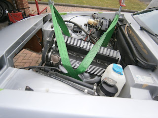
Out of the garage!!
The motor could then be lowered into the vacant space at the front of the car.
Lowering the motor into the car

But whatever I did, the clutch splines would simply not slide onto the gearbox shaft- alignment it seems, needs to be near perfect. I could tell there was no engagement because if the car was put into gear the motor could still be turned- so not connected to gearbox then! After 5 hours I was forced to admit defeat and took the motor out again.
Motor wouldn't slide back onto gearbox shaft splines.

This pattern was repeated on two subsequent days... I simply couldn't position the motor. Here is a list of what I tried:

1. Although I still think it is necessary to fit the LHS side engine mounting- the rubber insulating foot of this does really get in the way so I removed it leaving the leg still attached to the block to get a bit more manoeuvring room.
2. I tried raising the gearbox up against the transmission tunnel- (increases slope of the shaft) some people report this helps.
3. I used a laser level placed on the gearbox shaft to try and gauge the desired position for the front crankshaft pulley and thus the angle at which I need to hang the motor to match that of the gearbox shaft.  This helped but didn't allow a good fit because of the lack of control over roll positioning as mentioned above. I think its worth documenting though so pics below.
5. I tried a bore scope inserted through the clutch operating  arm opening- didn't really help, it was very difficult to see the parts you needed to see to gauge what was fitting and what was jamming. 
6. I tried some guide rods to position the motor on the gearbox- this was useful so pics below.

Laser positioning
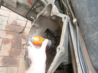
using a laser line to work out front crank pulley position to align with gearbox shaft. Note bell house raised up against transmission tunnel.
 I placed a sheet of plywood (left over from crash panel manufacture) just in front of the rad mounting bar and turned on the laser--spot was there honest!
 Sliding the laser round the shaft described a circle within which in an ideal alignment the front crank pulley would sit
 Or in other words... the pulley centre nut needs to be 17.5 Cm up from the oil cooler mounting bar and 30 Cm in from the RHS bulkhead seam when the bell housing is against the transmission tunnel.

Circle described by laser pointer

engine turns out to be at a rather smaller angle than I expected

Going in- but too steep
adjust pulley to height

Line up rear by pushing in sling to roll engine- too heavy to hold.
 Well this looked really promising... but I was defeated by the roll question. The motor would slide back but would always foul on the two alignment dowels. Holding it rotated to the right position was impossible if I needed to push it back at the same time... you really do need a couple of burly mates! However as all my friends are the same age as me and all have similar bad backs that's not going to happen!

Guide rods
One suggestion from the excel.net forum is to fit long temporary M10 threaded studs as guide rods to ensure that the cases match as they are eased together


I cut four 4 inch sections of M 10 studding and checked the threads still worked

Screwed these into the bell-house mating slots (inc the dowel sockets) around the motor.
I used these to align the motor

as shown
I could then push the motor backwards and by rotating the crankshaft I did eventually get the splines to engage- this was not straight forward and took a couple of hours but at least it was possible this way.

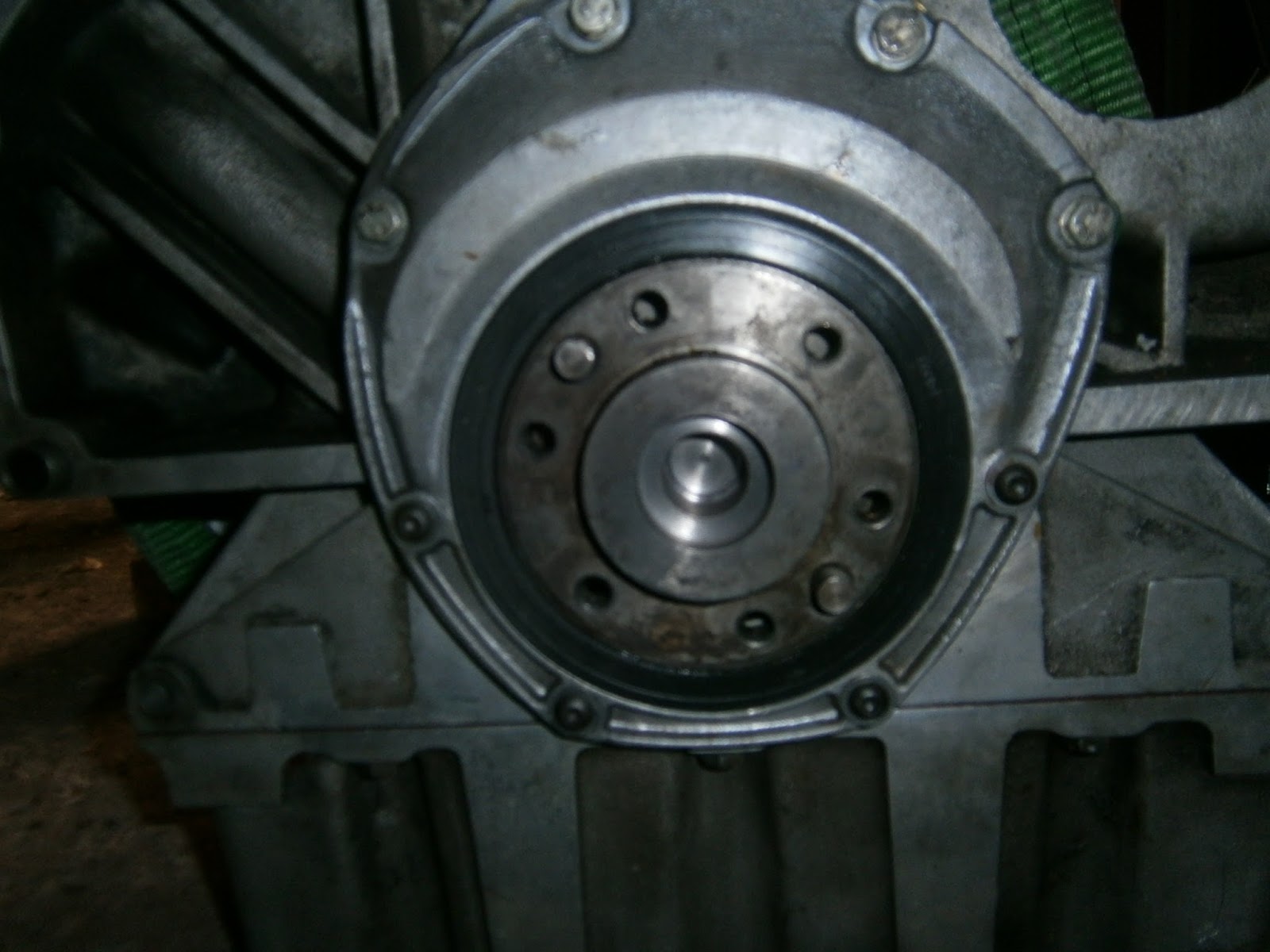
Unfortunately- although the top bolts could be easily fastened, the lower bolts didn't tighten up. The dowels did start to enter their sockets so I am confident that this wasn't the problem. It seems therefore that the crank simply doesn't fit onto the gearbox shaft and the 3mm gap or so that is left is about the shortness of the drilling


Lower bell house mounting bolt clear gap at bottom of motor


Residual gap- extends up the side, dowel is engaged in its socket, bolt tightened by cannot close up the gap.
Dowels are almost engaged, note residual gap between the crankcase and bell house on the other side too
So the conclusions from this are that the guide rods certainly help in motor installation;  but that the motor itself does not fit.

What now?
Discussion with Lotusbits Mike Taylor support this conclusion. I'm not absolutely sure he understood my position- although this is a 1982 Eclat motor I think its an Eclat Excel rather than a pure Eclat as it lacks the wing-like projections on the sump used as engine mountings in the Eclat and there is no sign of these having been removed. Of course its always possible that the whole sump was swapped for the later style when the flywheel was modified, but in any event it suggests to me that this motor has already been used in an Excel at some stage in the past. In any event, he suggested three courses of action- two of which I had already guessed (modify/swap the crank) although a third involved fitting a later style  bell house and engine mounts which would move the motor forward 1 cm and thus provide clearance for the gearbox shaft.

1. I'm not really happy about trying to move the motor by inserting a wider bell housing; there isn't much room and the changes in engine mounting requirement were confusing. Even if I did this I suspect it would lead to knock-on problems with the exhaust and other fits/clearances... does it reduce spline contact length for instance? Its easier to try it alone at home, but its not actually that much cheaper with bell housings (used) coming in at around 100 quid and engine mountings at around 60 quid each. Total cost about £220

2. Fit a replacement crank: A bolt-in  replacement reground crank is £300, and I could specify the regrind size so that it fits with the +10 and +20 shells I have bought and fitted during the rebuild.

3. Use my existing Excel crank  (in the old Excel motor): If this hasn't already been worn or  ground too far, it could be reground to fit with my shells as above. This is likely to cost around £150 and thus appears to be the cheapest option. However I don't know that this crank is suitable for regrinding to these specific dimensions and removing it would reduce the likely second hand value of the whole spare motor so there would be an additional cost there.

4. I could have the auto motor crank machined to provide the required clearance: This  would convert the valueless auto crank to the more useful manual version and preserve any resale price in the short motor. This is probably the best way to go for a crank swap as I know the crank is good and it already fits with my new shells. Cost for this is around £150

Options 2-4 involve stripping the motor again, and this would also mean adding the cost of new gaskets, oil seals and sealants to replace those (all new) ones that I have just fitted but which would be destroyed in this process! They thus carry extra costs. Also of course it will be a lot of work... BUT... I have found a company (Myanengineers) who claim to be able to machine the crank (giving clearance at the front and recessing the spigot bearing) whilst it is still in the motor! It does mean driving everything down to Bristol, but so far its the simplest option meaning less work for me - although one of the pricier at £210 plus petrol. I will try them and let you know how it goes.