Getting the crank modified.
As far as I can tell the main problems are twofold-
Firstly, the splines of the gearbox shaft (or perhaps the conical shaping beyond them) fouled on the front of the flywheel because this isn't drilled deeply enough.
Secondly, the spigot bearing isn't recessed far enough into the crankshaft to allow the shaft to slide in fully. I'm sure there is a wealth of Freudian comments but sadly all escape me at present. The sum total of my investigations is shown below:
 |
| This is the crank boss as it is and my drawing below |
 |
| This is the central crank boss as present on the automatic motor. Central opening is narrow and shallow with the spigot bearing recessed only 3 mm from the flange edge. This is achieved by limiting the accurate reaming of the bearing hole to 18.5 mm depth. |
 |
| This is what I need- the central boring is enlarged to clear the splines on the gearbox shaft (28.5 mm diameter). I have suggested boring to 32mm to provide enough clearance and deepening this bore to 9 mm. I've drawn this as a milled out flat bottomed recess but a conical section is also fine as long as its deep enough. At the same time the spigot bearing hole is not enlarged, but reamed to an additional 7 mm depth (25 mm) to accept the bearing in a lower position. |
The spigot bearing measures 21.002 mm in diameter in a digital micrometer, so the central hole is presumably slightly less than this. The best I can gauge from calipers is 20.82 mm. However I lack the tools to measure this internal dimension accurately. I will leave a spare bearing with the engineers so they can test the fit.
I am also a bit mystified about the depth of the spigot/pilot bearing hole. My investigations using a wide drill bit suggested the the manual motor is drilled some 3mm deeper. However measuring the depth with calipers finds the same depth in both. I think this must indicate the drillings have different end profiles and the auto motor tapers more sharply. I will try to get it deepened by 3mm over an 18mm diameter which should accept the gearbox shaft and give enough side clearance for the machining to avoid damaging the section already reamed. Note: this is not shown on the drawing!
In the meantime I removed the alternator and PAS pump and associated belts to help access. I did also remove the cambelt but the company didn't want to risk machining with no belt in case the crank rotated a little so I will refit that today- seems a sensible point!
The next big problem is how to move the motor. I collected it on my trailer... This is a single motorcycle trailer but I made a detachable flat bed out of plywood a long time ago to accommodate non-motorcycle loads. This was fine for collecting the motor- BUT at that time the head was off. Now its connected the unit is heavier and very much top heavy so its unstable. I must get it fixed in position.
Well that was a real nightmare. I don't necessarily recommend this but if you are faced with the same problem this at least is one solution! Eventually I opted to fix a 10x5cm wooden frame around the sump. The front section was cut to 9cms height so that it could pass under and support the smaller sump depth at the front of the motor which hung over the frame. I also cut a short section out of the RHS frame to accommodate a projection in the cases. This frame was fixed to the wooden bed of the trailer to prevent to/fro and fore/aft sliding; the whole being positioned along the line of the trailer axle to avoid placing excessive vertical forces on the tow link. Also it makes the trailer much easier to move when the motor's weight need only be pivoted (not lifted) when raising the front to attach/detach the tow ball.
The motor was top heavy owing to the inclined head and tended to fall onto its exhaust side even when the sump is square on the trailer bed. To oppose this I fitted 4 props to support the motor upright. The first two were 37 cm struts of 8x5cm timber fitted with a square-cut end under the exhaust manifold. Their other ends were cut at 45 degrees which allowed them to sit flat on the bed. I fixed another cross member behind these for added strength. I cut another two struts from 6x4 cm. These were 40 cm long and their square-cut ends were fitted above the exhaust manifold supporting the head and screwed at their lower ends onto another cross baton of 8x5 fixed to the bed. Their lower ends being cut at cut at 45 degrees to sit flat on this cross brace. When these props were screwed into place they supported the motor to stop it toppling, but as they were fitted into the concave side (exhaust side) of the inclined motor, they had to be unscrewed before the motor was removable from the trailer.
 |
| Making the sump frame- 10cm timber. Note slot cut to accommodate projection in sump at motor RHS. Note the front of the motor overhangs the frame and sits in the 1cm cutout. |
 |
| Front timber, 1cm cut off the top giving a 9cm height to pass below and support the front of the sump |
 |
| View of both sets of props, the two forward props fit against the block below the inlet manifold and are braced at their bases. The upper pair of props fit against the head above the exhaust manifold and are screwed to a cross batten at their lower ends. Later I put two cross pieces to help steady these in the lateral direction. |
 |
| Side view (rear of motor) showing sump cage rear and RHS. Both sets of props visible |
 |
| Both pairs of props in close up, upper pair yet to be screwed down. |
 |
| Overview- note props yet to be screwed down. |
Once I was happy with the security I removed these steadies and took the motor out of the trailer to fit it properly. I plugged all the open holes and covered the top of the motor with plastic sheeting. I then covered the cradle with a tarp before lowering the motor in on top. The tarp was then wrapped around the motor (inc the strops which were left in position) and secured with duck tape.
 |
| Wrapped motor in cradle- note props fitted outside the tarp. Steadies added to cross-link the two upper props. |
 |
| Ready to go |
Finally the motor was tied down with ratchet straps. This arrangement was very secure and withstood the journey well. The coverings also protected it from torrential rain on the way.
This is the machine Myanengineering will use to work on the motor- Its from the aero industry and can manoeuvre loads of up to 3 tonnes in order to position them correctly for machining. Very impressive; it should cope easily with my motor.
 |
| Machining in progress. |
Well its been 3 weeks... but I heard today the motor is finished. I will get down to collect it next Tuesday so wish me luck!!
 |
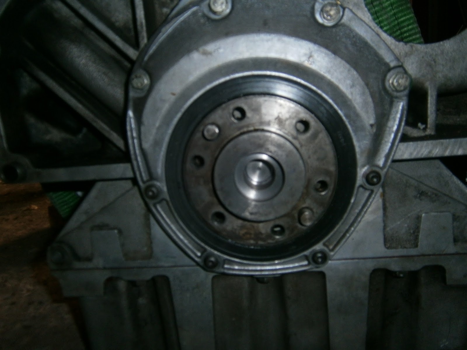
| Motor as received ... the face has been opened out and if you zoom in the new reaming at the base of the spigot bearing socket is clear. |
|
| And for comparison... as sent! |
Well the end has certainly been modified- there should be enough room now for the gearbox spigot. I am slightly concerned that the spigot bearing is no longer such a tight interference fit in the crank end so I will use a little Loctite retaining compound to help fix it in place.


No comments:
Post a Comment
Feel free to let me know what you think of this blog. I'm working on my own here so any feedback from those Lotus enthusiasts floating around "Blogger Bank" is welcome. Suggestions for process improvements especially welcome. If you like it please follow.