Search for tasks- type in keywords

Monday 23 October 2017

Why am I going through batteries? Alternator charging, current drain and CORRECT radio connections!.

I've had this car for about 3 years... in that time I have rebuilt much of her and driven the princely total of around 400 miles... I have also used 3 batteries!

The first was a high capacity battery I thought would last throughout the rebuild... but as it sat for nearly 2 years untouched I wasn't all that surprised when I found it was dud. I fitted a second (Varta)  when I started rebuilding- this lasted app. 6 months during which time I drove no where at all but developed the same faults as the previous battery- always discharged- wouldn't charge up to full capacity and discharged when left alone. I tested the current drain rate and found it to be 0... and also checked alternator charging and found that I had a stable 14.4V across the battery with the motor running. This  seemed high to me as I've had a motorcycle regulator problem resulting in battery death at just 14.7V in the past. However, I was assured that 14.4 was perfectly acceptable in this car and so I attributed my problems to a duff battery and blamed the suppliers... possibly wrongly. Anyway, assuming my problems were due to a bad battery, I bought a Lucas 075 unit and all was well. I finished the car, but even then I did find the battery discharged on occasion- once indeed whilst it was at the garage during its interminable wait for an MOT. However I drove the car frequently- amassing my 400 miles usage and then- yes you've guessed it, I left it for a couple of weeks or so and it was fully discharged again! The Lucas battery has started to loose charge just like my previous battery which I had assumed to be faulty. The only thing I hadn't checked was rectifier function so I tested for AC at the battery and and found none- again I have had rectifier failure on a bike in the past and AC will really brew up your battery quickly!

Well that's eliminated everything and yet I still have a problem. Here its confession time!!!! I am an idiot, a charming and enthusiastic idiot its true, but nonetheless an idiot.... it turns out that multimeters have an internal fuse that affects only the ammeter functions.... and yes, of the three meters in my possession not one had a working fuse! All therefore gave me the same reassuring but completely meaningless value of 0 for current drain and as all worked perfectly in every other respect I didn't realise I had a problem... however, replacing the fuses showed a completely different situation.

I turned off the ignition and radio, shut the doors and connected the meter in series with the battery. I found a current flow of nearly 140mA!


Apparently 50mA would be considered high so this was huge! The boot courtesy light was on in this test and turning that off reduced the draw by 36mA (I have an LED fitted not the usual festoon bulb).


This still left a current draw of over 100mA- and given my battery is only 50Ah, this would drain the battery completely in 500 hrs or  20days, probably making it impossible to start in rather fewer. This probably explains why I can't start the car if its left for a week or two! The only problem is that the only thing that should be drawing current under these conditions is the radio... and here a glimmer of recollection began to flicker!

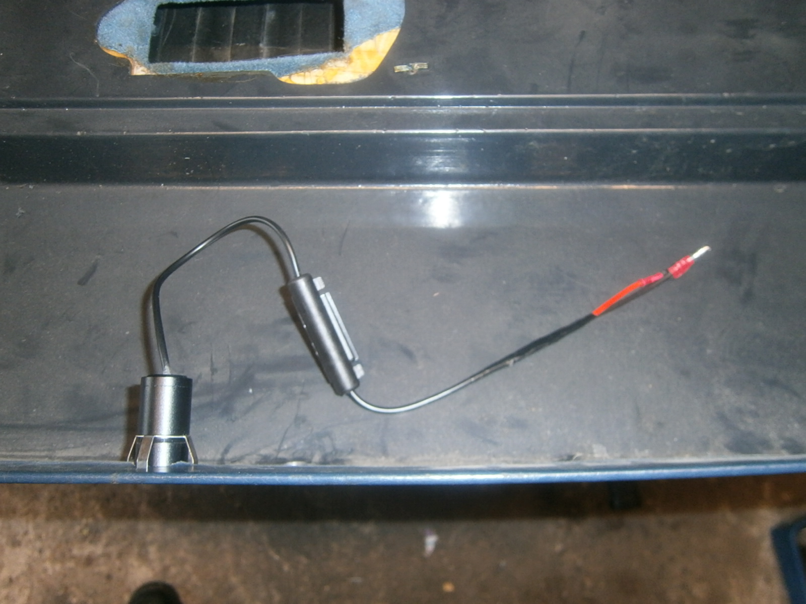
I don't have a manual for this radio (Sparkomatic 309- if you have one and can send me a copy please get in touch!), so when I swapped my radio for the newer version, I had simply adopted the connections that were already in place in the car (see my post here). I know that the radio will have two live feeds, a switched live to run the actual radio and a permanent live to keep the internal memory and clock when the car is switched off. In my case I had found that both of these were already connected to a permanent live. I hadn't thought this would matter since the only things that should be drawing current when the radio is off are the memory and clock functions- both of which have only a small demand. Turns out this isn't entirely true- here I was shafted again by the dead cold hand of the LBPO- I really should have learnt not to trust anything he did, but without a manual I'm sorry to say I knew no better! Luckily I have a spare radio unit, identical to my own but with a duff tape deck, but I can certainly use it to check current draw.

I connected the old radio as  it was in the car- i.e. both lives to the battery positive and the case to earth- shock, current draw was 80mA!! Disconnecting the red/white wire saw the clock extinguished and draw fell to zero. This however rose to 250 mA when the radio was turned on. The clock remaining off!
Disconnecting the red wire saw the current draw drop to 6mA, regardless of whether the radio was turned on or off, and the clock remained extinguished throughout!

This then is the heart of the problem: The clock display function seems to require a Hell of a current at around 74mA! The display is only illuminated when both feeds are live and this is expected only to happen when the motor is running! The clock is not meant to be visible in a parked car with the motor off, yet this is how it was fitted in my case. This analysis has also allowed me to identify which feed is which and the permanent live feed  is the red/white wire; the switched the red. Later radios would have this permanent feed as a yellow wire so its important to realise that its different in these early radios.

I pulled a few fuses to check how the radio was connected. In my case both feeds drew power though a permanent live via fuse 3. Removing fuse 3 saw the current drain fall to zero!


The Lotus manual wiring diagram shows the permanent live should be connected via a purple wire to fuse 3 and the switched live via a yellow and green wire to fuse 18. I am hoping both of these wires are still in position even if unused. Thus as a minimum fix to solve this problem I need to disconnect the red wire (switched live) and reconnect it to fuse 18 through the yellow green wire which should already be in place- unless removed by the LBPO.

I removed the knee panels again and looked carefully in behind the radio. The purple wire was easily identified. It was connected through a double bullet connector to a brown wire terminating in an unused bullet and even bearing a ballast resistor. Similarly the green white wire was also present and terminated in an unused double bullet connector. The radio was not connected to either of these obvious connections . I was able to cut out the cumbersome extra wiring and rationalise so that the red/white wire was connected via the ballast resistor and brown fly lead to the correct purple feed and the red wire connected via a bullet to the correct green and yellow wire.
Purple/brown/ballast resistor feed connected to red/white wire as permanent feed.

Red switched live  connected to green yellow feed.
 I incorporated in-line fuses in both lines. This reconstituted the correct connections and the radio clock now came alive only when the ignition was turned on. Connected in this way, current draw had now decreased to 7.5 milliamps (pretty close to the draw related to memory/clock maintenance as determined in my bench test, and  battery charge life correspondingly increased to the order of 260 days!


Well having installed the radio I am struggling to find out how it shoyld operate.  There seems to be no manual for the installation and use of the radio although I will keep looking.  The company suffered a serious fire that destroyed many Te cords and brochures and as this was always a rare stereo in the UK the chances of finding a replacement are few.. . If you have one and can send a copy please let me know. In the meantime Im comparing mine with similar midels. .  This one at least gives some hints. 


Fitting logo puddle lights; ghost shadow lights

I fancied fitting some logo puddle lights- although these were usually very expensive. I found these LED logo sets on eBay at around £16 which I thought was great value.


Inside the box you get both light units and even a hole saw!
 The light units come with generous flex. The fuseholder-like object actually contains a box of electronics of unknown function! This complicate fitting a little.
The front of the unit unscrews to reveal the logo hologram disc- here released.

These units are made to install into the base of the door. However the GRP doors of the Excel are too narrow so it can be installed in the base of the trim panel. However make sure you fit it far enough towards the inside of the car that it will clear the moulded strengthening ribs on the inside of the door.


Use tyhe hole saw to drill through from the inside of the trim panel
The object is to remove the disc of GRP but not to cut through the trimming leather itself. Use a sharp knife to make diagnonal cuts from the centre to the side of the hole creating triangular sections that can be folded backwards. Then, using a flat object like a lolly stick, work some leather glue in and under the trim leather, pressing it back into position so that it sticks around the edges of the hole. Then using a sharp knife trim away the leather covering the hole to leave a neat edge stuck down to the door.


At this point I test fitted the light


I intended to wire up the light through the door edge feeds. Power enters these through the purple wires and flows to earth via the purple/white. This means that the positive red of the lights has to connect to the purple and the black to the purple white. LEDs must be connected the right way round to work.


However the connection has to be detachable or the door panels would become non-removable. This means using a connector and as the LEDs draw only a tiny current they come fitted with very fine wire- far too fine for normal crimp connectors, so I soldered lengths of standard 5 amp wire after the electronics box.
Strip back the outer covering revealing the inner black/red wires. I used my finger nails to strip the insulation from these over 10mm or so.
 
 I wrapped them round a stripped 5a wire...
 ... and soldered the connection
 ... before covering in heat shrink
... and finally wrapping the join in insulating tape. The idea here is to strengthen the join and provide rigidity as flexing around the soldered length would very soon break the thin wires.
Finally I was able to crimp a bullet connector onto each of the thicker wires  ready to join with the door edge feeds.


Finished light installed.
Do not screw the cap tightly up against the light body, the idea is that the spring feet will exert enough pressure to maintain tension on the cap and  keep the light secured, but if there is some free play in the thread then the cap can be turned underneath the door to orient  the logo projection and make sur eit projects the logo the correct way up!
Door edge light removed. Note the gaps made in the wire using an automatic wire stripper to cut and push the insulation along the flex.
I removed the edge lights and used an automatic wire stripper to make a gap in the flex to connect a feed wire take off and then pushed a sharp point through to make a junction point.
I prepared 5 amp wire fly leads by  fixing a female bullet connector to one end and stripping the other to join onto the edge light wires, and I could then feed the free ends through the edge light feeds and wrap the wire around the exposed section to secure.

This makes a firm and strong join without solder but just to be sure I did apply a blob of solder to each.
Finally I covered the joins in heat shrink. Obviously when you make a join this way you have no free end  to feed heat shrink over- in this case the free end has a terminal so I had to use a wide piece of heat shrink- too wide really to contract properly...

... so I also wrapped thelot in insulating tape.

The new wires need to be brought forward out of the door cavity through a hole drilled under the door's strengthening ridge so that it can lie along the inside of the trim panel. I could then fit the trim panel and reconnect the speaker as well as linking up the feed for the puddle lights. This completes the installation- I will try to get a picture of the projected light effect when its dark enough! 


Installing a fan monitor light and otter bypass (over-ride) switch


My nerves and the otter switch are in constant battle- probably because on at least one occasion the switch has failed. I have renewed the otter switch but somehow I can't quite bring myself to trust it fully and sitting in traffic is pure torment. I find myself watching the temperature gauge and waiting for the fan to switch in. However, as things stand there is nothing I can do as the temp creeps up and I can't tell if the switch is late until its too late! What I therefore need is firstly a monitor light which will activate whenever the fan is active and a bypass switch that will allow me to turn it on manually if I suspect the motor is becoming too warm. This is also useful to decrease the motor temp just before parking as the fan will not operate once you have parked and the ignition is off, Leaving the motor with a heat build up just as you park isn't necessarily a good idea- I note modern cars do have fans that can run on after the motor is off.

The wiring diagram shows that the otter switch functions to connect a yellow green (YG) switched power feed to a brown/orange (BO) wire that earths via relay no 3. This closes the contacts and energises the fan. Power flows from the relay to the fan motor through a thicker brown and black (NB) wire.

In order to fit a bypass switch I need to connect a jumper switch between the YG and BO wires. I could connect this from the otter switch itself, but these wires are also accessible at the relay, and connection here would be neater. However the relay connections are all hidden away behind the fuse panel in the drivers footwell, and access is as always, very tricky! To get at least some chance of making these connections I unscrewed the 2 x 10mm bolts that secure the fuse panel.
Fuse panel is held by two 10mm bolts- lower one has been removed already
The fuse panel can then be pulled forwards- revealing a mess of wires at the back. Unfortunately relay number 3 is at the back even of this lot!

I was able to reach through and tease out the two B/O wires entering the relay
Fingers have just managed to grab the two BO wires 
These wires are very tight and have virtually no slack. Cutting and rejoining will be very difficult. I was able to get the automatic wire strippers in to reach the wires and open up an internal gap  in the insulation to which I could connect a red fly lead as an internal splice and then wrapping the join in insulating tape. 
Fly lead for switch bypass- still to be wrapped in insulating tape.


I was able to pick up the green/yellow switched feed under the dashboard at the point I had previously used to  connect the radio. This had been equipped with a double bullet connector so I simply used the other bullet available! When this wire was touched to the fly lead from the BO wire with the ign on, the fan sprang to life showing that the connections were viable.

If you look closely in the pic below you can also see the thicker brown and brown/black wires that also connect to the relay and supply power to the fan. Both are positioned just below the red fly lead connection shown above. 
Fly lead for switch bypass- note thicker brown and brown/black wires (power feed to fan motor) below fly lead connection- again access is awkward.
I created the warning light connection by making an internal break in the insulation of the brown/black (relay-to-fan motor) wire in exactly the same manner as that in the BO. I could then bring this fly lead forward, adding a 0.1a in-line fuse and connecting it to a warning light. I connected an earth to the other side of the light. This light will then illuminate every time power passes down the brown black wire to the fan motor- is whenever the fan is in operation whether it is switched by the otter or the bypass switch.

Finally I installed the warning light and bypass switch under the dash.and tested operation. I still need to tidy away the wires but the circuits are operating as expected.

Bypass switch and warning light installed in mini panel beneath the dashboard.
 Wiring shown below:


Monday 9 October 2017

Fitting a lights left on alarm buzzer

To my mind its surprising that a luxury car from 1984 wasn't fitted with a lights-still-on alarm system at the factory. It wasn't particularly high-tec and other cars of the period were already so-equipped. However, my Excel doesn't have a warning buzzer and I've already left the lights on several times and run the battery down once- even in the 300 miles or so since it was recomissioned! I have changed the panel-lights, sidelights, number plate, interior and door-edge lights for LEDs which should help preserve the battery, and leaving the headlights on isn't really a problem as the pop-up action is an obvious reminder, but even so leaving the side-lights on is a bit of a bind.

I decided to fit such an alarm. There are several ways to do this- the neatest is to pick up the relevant feeds behind the dash and at the rear of the lighting switch and route them to a new lights warning relay mounted somewhere out of sight behind the dash... Something like the RLYBUZ from Car Builder Solutions. A cheaper alternative is to use a simple buzzer (obtainable from eBay for a couple of quid) to let you know if you've turned the ignition off but left the lights on. Again there is a neat and a quick and dirty way* (*actually 2 ways at least) of wiring this in and it isn't as good as the real above.

However... I am strapped for both cash and time at present and I don't want to strip out the dash again- in fact I don't want to have to dismantle anything if I can help it, so the fitting needs to be quick and simple- so dirty ways it is!

I bought this buzzer from eBay- there are a lot of these out there and I think they are all pretty good. I have been warned that some can be drowned out by the sound of a gnat farting in a hedgerow, but both types I bought were pretty loud enough. Anyway check the buzzer function and volume before fitting. This is a simple buzzer-only kit and its wired in simply as well- I tried it first, but to cut a long story short it wasn't completely successful, so scroll down for the system I eventually fitted.

This is the cheap buzzer I bought- its pretty loud and even comes with a sticky pad on the back for fitting
These buzzers draw a very low current and being made to a price, have been fitted with the cheapest and thinnest wire possible. Its far too thin to handle conveniently so I soldered some "normal" wire on so I could make the connections conveniently.
Soldered joints to normal wire- covered in heat shrink
The buzzer will sound only when there is a voltage difference across the terminals and a current can therefore flow. If both terminals are at 0V or at 12V then there is no such voltage difference, no current and so no sound. The idea is then to connect the positive lead of the buzzer to anything that's live when the lights are on, and the negative lead to anything that is live when the ignition is on but earthed when the ignition is off. Again I am sure that really clever connections could be made behind the dash but the dirty ways of making these connections is firstly to connect by wrapping wires around the relevant fuses (Noooo!!!! even I baulk at that!) or as a second choice, use one of the light feeds themselves. I opted for that choice and picked up my positive connection from the sidelight power feed in the right headlamp pod. Make temporary connections just to be sure it works before going ahead.

My headlights are out at the moment as I'm still midway through replacing the bumper, so access here was easy. As the sidelights have been removed I had a loose bullet connector (red/orange wire) which I could use so I fitted a bullet connector to the end of the thicker positive wire from the buzzer...
Bullet connector (Lucas) attached to the buzzer positive feed.
 I will use a double bullet connector to join this wire to the sidelight feed.

Working from inside the car I threaded a section of curtain wire through the bulkhead grommet and into the engine bay, pulling the wire through. I then routed this along the RHS of the engine bay and attached it to the existing run of the loom along the side bulkhead.


Before passing beside the radiator and into the headlamp pod via a hole drilled in the plywood crash panel.

Wire routed through plywood crash panel
Double Lucas bullet connector for sidelight connection.

At first I found a ignition controlled live/earth by trial and error with a voltmeter. I found all the green wires entering the two multi-connectors just above the fuse box would be suitable.

Buzzer connected. Note the interruption block in the green ignition fed wire at the top which feeds power to the buzzer via a blue wire

However, connecting the buzzer in this way wasn't satisfactory. The system did work in that the buzzer sounded when lights were on and ign off, but there was a lot of "leak-through" interference. The buzzer sounded during normal driving- very faintly and in pitch with engine speed and this was clearly not acceptable. I tried moving the switched live/earth connection to the red switched power feeding the radio, and which already had a spare bullet connector vacant (see "Why am I going through batteries"). Sadly this made no difference. Its possible that a suppressor capacitor might have helped, but a better solution  is to mimic a standard lights left on relay and the wiring for this is available on the web. Using a standard 12V SPDT (normally closed) relay its fairly straightforward. The relay with base and pre-fixed wiring is available on Ebay for £2.50, a dedicated integrated relay and buzzer is around £15!
Relay and base unit (pre-wired)


This is the base of the relay (wiring base removed) 

Terminals 86/85 energise the internal solenoid.
Terminal 30 is connected to  87a when the relay is not powered, but switches to 87 when the relay operates.  
Terminal 87 is used as a parking position and will not be connected to anything.  

Wiring was obtained from the web, taken from here
For operation  Pin 85 is connected to switched live/earth and pin 86 to earth so that the relay will operate whenever the ignition is on. Pin 30 is connected to the lighting circuit (lights on power) via the lead wire I had already installed from my sidelights. The live buzzer connections are then made  to terminal 87a and the negative buzzer fed to earth by piggybacking onto pin 85. 


 When the ignition is on, pin 87a is disconnected and parked to 87. Power entering at pin 30 from the lighting circuit can go no farther, so lights on, ign on- no buzzer. Should the ignition be turned off pin 87a is switched back into power supply from pin 30, and if the lights are still on, then the buzzer will sound until the lights are turned off and power supply to terminal 30 is interrupted.

In the base received with the relay pins 87 and 30 are fed by green wires, pin 86 by white and pin 85 by yellow. I wired the buzzer between 87 (green, buzzer +ve) and 86 (white, earth, buzzer -ve). I soldered all connections and covered them with heat shrink tubing and zip tied the wires and buzzer to the relay  to avoid stressing the connections.


I attached terminals compatible with those already in place and fitted the assembly into the car. I used the radio switched live as the live feed . There was a handy hole already in one of the under-dash panels that I could use to mount the assembly.
Overall this was much more successful. The wiring is a bit chaotic since I have already fitted the fan bypass switch. I'm forced to use non-standard colours as I don't have the appropriate cable colours and  pre-wired components are joined to my wires often resulting in a colour change...nightmare! However I defaulted to red for anything that can supply power and black for any earths. I will make and fix some labels to these wires as I can't guarantee I will remember what is what in a few months time!

However, overall dead pleased and I will make up a similar component for my MGB.