I fancied fitting some logo puddle lights- although these were usually very expensive. I found these LED logo sets on eBay at around £16 which I thought was great value.


These units are made to install into the base of the door. However the GRP doors of the Excel are too narrow so it can be installed in the base of the trim panel. However make sure you fit it far enough towards the inside of the car that it will clear the moulded strengthening ribs on the inside of the door.

Use tyhe hole saw to drill through from the inside of the trim panel


At this point I test fitted the light


I intended to wire up the light through the door edge feeds. Power enters these through the purple wires and flows to earth via the purple/white. This means that the positive red of the lights has to connect to the purple and the black to the purple white. LEDs must be connected the right way round to work.

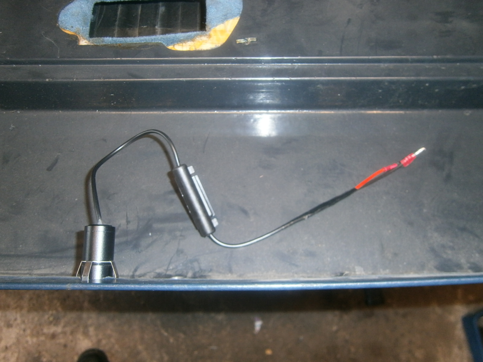
However the connection has to be detachable or the door panels would become non-removable. This means using a connector and as the LEDs draw only a tiny current they come fitted with very fine wire- far too fine for normal crimp connectors, so I soldered lengths of standard 5 amp wire after the electronics box.
Strip back the outer covering revealing the inner black/red wires. I used my finger nails to strip the insulation from these over 10mm or so.

I wrapped them round a stripped 5a wire...


 |
| Finished light installed. |
 |
| Door edge light removed. Note the gaps made in the wire using an automatic wire stripper to cut and push the insulation along the flex. |
I removed the edge lights and used an automatic wire stripper to make a gap in the flex to connect a feed wire take off and then pushed a sharp point through to make a junction point.


... so I also wrapped thelot in insulating tape.

The new wires need to be brought forward out of the door cavity through a hole drilled under the door's strengthening ridge so that it can lie along the inside of the trim panel. I could then fit the trim panel and reconnect the speaker as well as linking up the feed for the puddle lights. This completes the installation- I will try to get a picture of the projected light effect when its dark enough!
No comments:
Post a Comment
Feel free to let me know what you think of this blog. I'm working on my own here so any feedback from those Lotus enthusiasts floating around "Blogger Bank" is welcome. Suggestions for process improvements especially welcome. If you like it please follow.