Retrimming
I am hoping that I can cope with the flat or straight sections; the roof panels and flat rails (the rear header rail and the roll bar cover). I will have to find a solution to the B pillar problem. However, I do not expect to be able to handle the front header rail or cant rail coverings. These curved rails all need multi-part covering to cope with their curvature. This means making neat joins between the sections (ideally sewn) and I'm not going to be able to do that. although I have read that making a stuck hem can give a passable finish. If not then I will have to take them for professional attention. I'm not intending to recover the sun visors.
 |
| Finger indicates the seam in the cant rail covering |
I don't think its feasible to give a step by step guide to this job- nor can I give you any templates because I'm cutting as I go. However here are a few snapshots of my progress and maybe you can benefit from my mistakes?
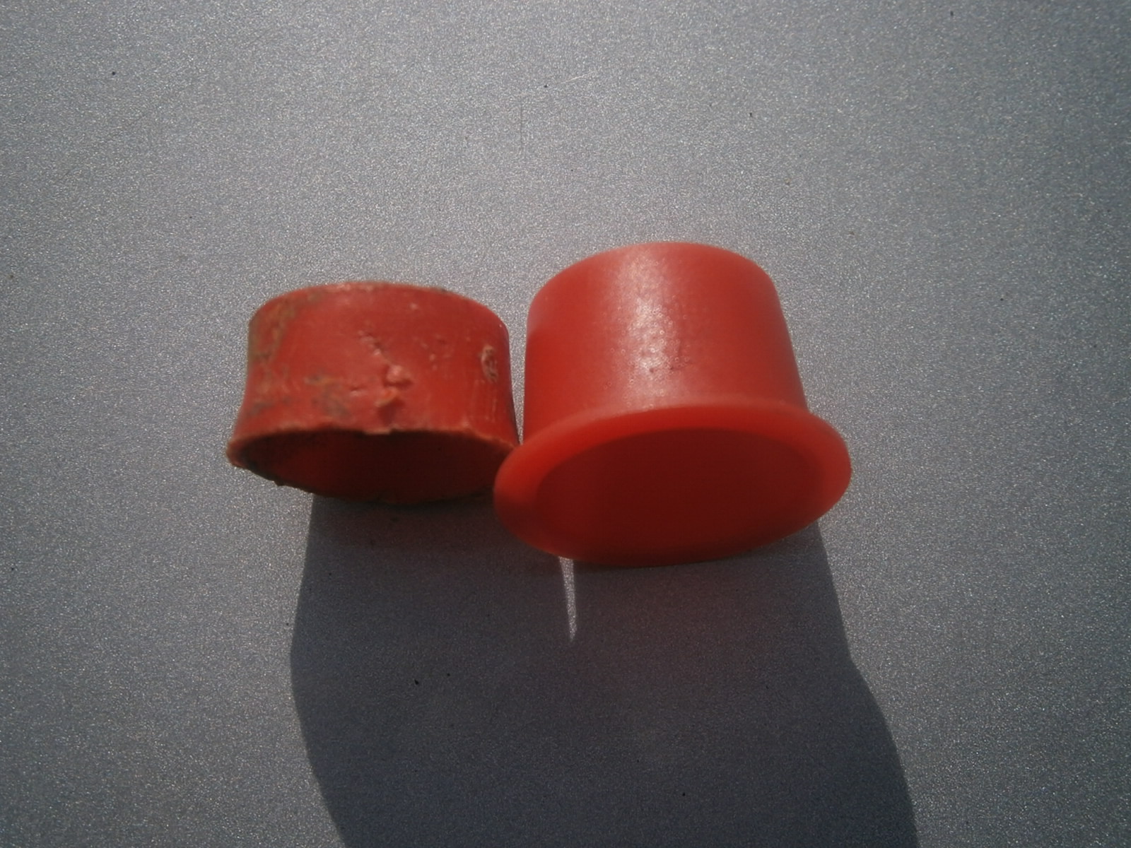
This is the glue I'm using- I got aerosol because I didn't think brushing onto a foam backer would work well. Its important to get temperature stable adhesives.
I used a wallpapering table and some ceiling lining paper to provide a clean surface. You need to flip, fold and change this very often to avoid putting a finished surface down on the old glue! I also had two pairs of new wallpapering scissors- I kept one for fresh fabric only and didn't use these with anything glued.
Rear Header Rail
Obvious place to start, this is a simple straight rail- well slightly distorted through heat my case. Anyway it just needs a straight 4" strip
 |
| Rear header rail and the strip of fabric cut to cover it. |
Surprisingly there isn't much trace of glue on the pieces I have stripped. Most sticking seems to be on the inside of the parts with the fabric stretched over the top and fixed again at the opposite side. The bulk of the top parts of these rails aren't glued at all.
I sprayed the edges of the strip and also inside the rail
 |
| Spray glue coating to edges of fabric (foam side) and inside the rail |
Before fitting the cover. I found that if you lay the rail on the adhesive coated fabric and just raise it slightly the edge will pick up the material on that side and you can ten roll it over to pick it up at the other side stretching as necessary.
 |
| Edges stuck inside the rail |
You have to cut darts out at the corners so that the ends can then be folded over too. Overall not so tricky for this part.
Roll bar cover
I cut a strip longer than the roll bar cover and wide enough to go around it completely with a 1" overlap., The roll bar is a bit awkward and I couldn't see how to start but eventually I laid it along the strip with the flattest edge down-most (without the cutouts) and with a 1" overlap of foam side. I could then spray along the whole edge of the rail- covering the inside to a width of 1" and also coating the exposed foam
 |
| Here I have sprayed the inside of the rail and the projecting foam beneath The vent cutouts of the rear side of the cover are uppermost |
Again rocking the rail upwards (towards the camera in the
pic above) allowed the edge of the rail to pick up the fabric which could then be smoothed over the edge and stuck to the glue inside the rail cavity.
 |
| Raising the rail by rocking it forward so that the lower (glued) edge catches the fabric |
I could then stretch the fabric over the top of the rail, but it wasn't clear where to start as the other side has several cut-outs of the vent panels and also a bulge for the rear interior light. I decided to tackle the interior light first. I placed the rail upside down with the glued edge on the table and sprayed around the light opening and backwards onto the fabric in an H shape

I then stretched the fabric over the light housing trying to avoid creases and pushed it firmly into the glued sides. I had to cut a couple of slits to relieve the tension and allow the fabric to fold naturally.

Turning the rail over I could cut some more darts around the edge of the light housing...
... and then fold the fabric over and glue it to the inside of the rail.
I could then progress along this side of the rail in each direction from the light housing. Spraying the inside of the rail and the overhanging foam in one go. I could then stretch the fabric round the rail, cutting darts as necessary to let it fold naturally. Its necessary to cut little darts into all the corners where the fabric can bend but its no a good idea to cut right down to the plastic as its easy enough to accommodate a little extra in your fold and this is much preferable to making a hole!
 |
| Folding fabric around the rail and over/into the vent cut-outs. I sprayed the inside of the rail and the underside of the fabric at the same time and then stretched it around and over the edge to stick inside the rail. You need to cut darts at each corner. |
The ends are quite complex- I don't think I did them right, but they will be hidden inside the top of the B pillar anyway. You need to think on your feet and cut diagonal darts as needed to allow the fabric to be folded into the various shapes. At the end think about which section will be folded over last and use this to hide any raw edges for other bits.
This is the roll bar cover as completed.
I cut out the light opening for the interior light by cutting a central long slit and then extending this as 4 diagonals into each corner.. This gave 4 tabs that could be folded through the opening and stuck on the rear.
 |
| Detail of the light opening and vent grill spaces. |
 |
| Interior light opening |
 |
| Fabric stretched around mouldings at the end of the roll bar cover. However this will be hidden inside the B pillar. |
Cant rails
The cant rails are the first of the components that need multipart covering. I have already indicated the seam. I am referring to the long thinner section of the rail as the stem and the folded upright region as the up stand.
 |
| Finger indicates the seam in the old cant rail covering, up stand section to left, stem section to right. |
I can't sew so I'm going to try the hem technique from Chris Wrights account.
The up stand on the cant rail needs a separate section of covering from the longer stem part.
I tried two approaches to generating the hem needed to hide the join. To generate a hem the idea is to tuck the end of one section under and glue it back on itself. Its much easier to do this with the fabric upside down (foam-side up); in other words working on the wrong side of the fabric. This means you can either use the RHS cant rail as a template for the left or do as I did and cut a paper template.
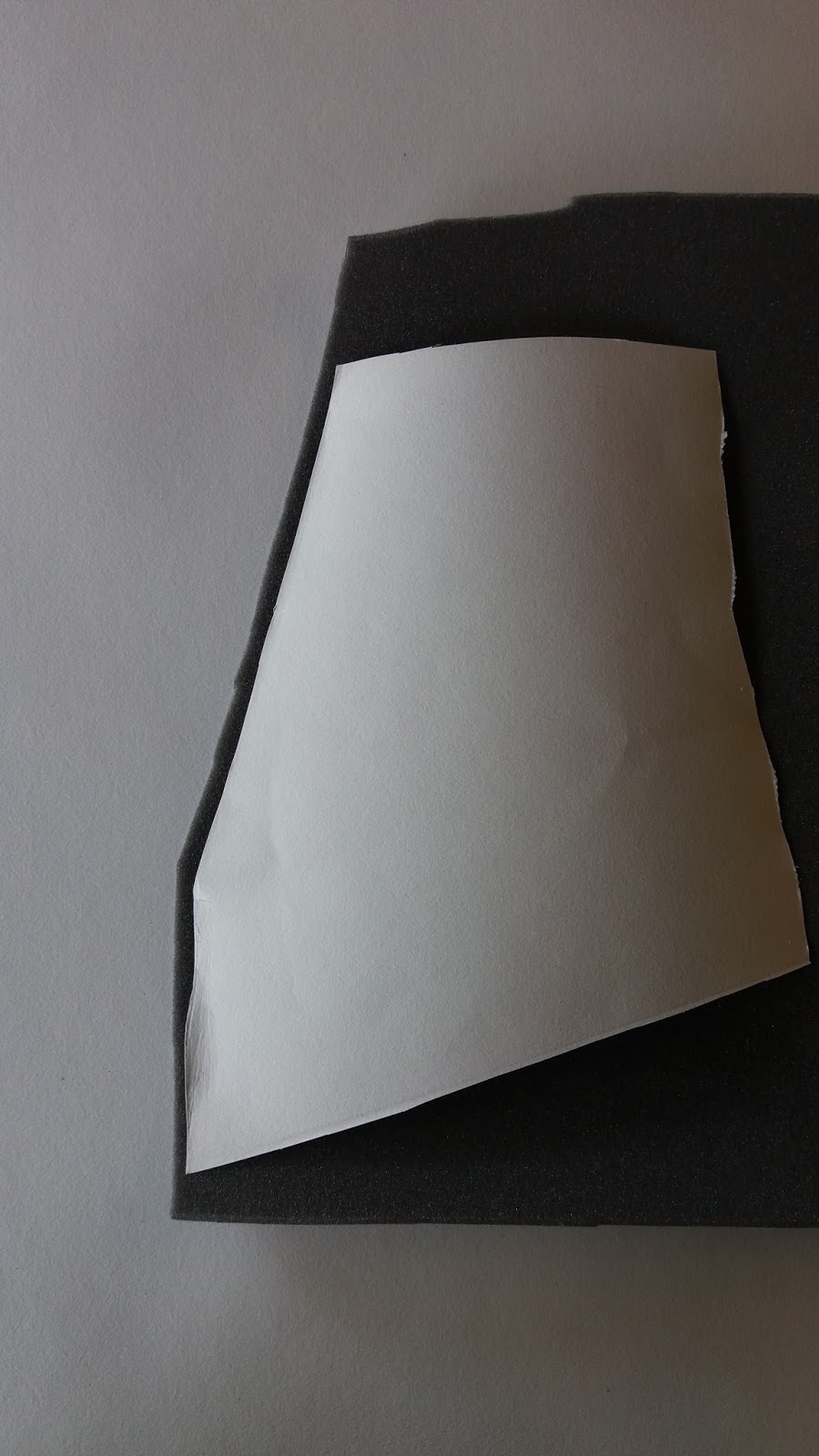
I cut a stiff paper template to give the end profile needed for the stem section. This is shown as if the headlining were face up.
 |
| Paper cut to profile of cant rail junction |
To cut the underside you need to flip the template over and place it on the wrong side (foam side) of the material.
 |
| Paper flipped over and placed on the wrong (foam) side of the fabric for cutting |
Next slip the template back 2cms or so from the newly cut edge
 |
| Slipping the template back 2cms |
You may need a dart at any corners
 |
| any darts needed? |
Holding the paper down, spray the exposed 2cm of the foam, let the solvent flash off and then fold the exposed section back on itself to generate a 1cm hem
 |
| Forming the hem |
 |
| Hem fully folded. |
Once the hem has been produced check that it will fit against the up stand section as required (right side up!).
 |
| Testing the hem for fit against the up stand section. |
 |
| Not a satisfactory picture but I basically cut, folded and glued as I went to cover the up stand. However you can cut a second paper template if required. |
I could then cover the up stand by folding the fabric over. I stuck it down progressively cutting darts and gluing sections as described for the rails above. I cut the section to fit against the stem section- no overlap is needed but anything up to 1cm will be tolerated.
Next, glue the underside (foam-side) of the stem section you have made around and over the hem and also apply glue to the junction with the upstand section- care to avoid over spray!
Offer this up to the covered up stand section aligning the profile and smoothing the section into place, hiding the raw edge of the up stand section.
Finally progressively spray, stretch and trim the fabric to stick it over the stem section as described. Completed section below - obviously not as good as a professionally sewn cover- but much cheaper!

Front Header Rail
This is undoubtedly the most tricky part so far. It took me two goes to get it half way decent and to be frank I think if faced with this job again I would resort to the professionals. I append how I did it but you might like to gloss over that and get yourself straight down to the workshop!
You have to remove the side rail clips-, these were pop riveted through the fabric originally (see my
interior mirror entry) so I took a couple of shots to show how they are fitted.
 |
| Header rail fixing clips |
Then I drilled out the pop rivets.

My plan for the header rail is to cover the side sections and then cover the bridging region with a hem at each end to but up against the raw edges at the sides. I'm going to need to trim the side sections to generate the correct profile so I applied masking tape to the rail as shown before spraying with glue to prevent areas to be trimmed for being stuck down.
 |
| Rail taped prior to starting the process. I am calling the horizontal section in this picture (contains the interior light housing) as the bridge section. The two side sections are vertical. |
Inverting the rail, I lined the covering fabric with the first side section and sprayed the overlapping inch or so as well as the inside of the rail.
 |
| Fitting the cover to the side section, spray glue onto fabric and inside the rail |
Raising the rail allowed the edge to pick up the fabric
... which could then be stuck down inside the rail.
 |
| Fist section glued over and inside the rail. |
I scored the fabric around the junction with the centre piece and trimmed it to fit. Check fit and then. lift the fabric and spray glue underneath and onto the rail itself. Peel off the tape to remove any over spray and stick the profiled section down.
 |
| Side cover cut to profile around the junction with the bridge. Note pay careful attention to the curves here or you will be left with gaps. |
 |
| Fabric glued down- note vertical edge of front section, this has to be cut carefully to allow for the curved surface and yet still give a straight edge. |
Spray along the inside edge of the side section as well as the overlapping fabric and then keeping the fabric taught, carefully fold it down and stick down into place. Note that the side sections widen and flare at the same time that the profile bends down. This means that you are sticking onto a curved surface and a straight-cut edge will generate a curve when stuck down. You need a straight edge when stuck as above and this actually means that you need to make a curved cut in the fabric. Experiment to find the cut you need to make
Cut darts along the curved regions so that the fabric can fold naturally around the curve.
 |
| Darts cut to allow the fabric to curve round the inside edge. |
|
|
Trim around the top edge and cut darts as needed to fold the fabric down
... to cover the end completely.
I covered the other side section in the same way.
The central section will cover the rail between the side pieces and should terminate in a folded and glued hem at each end. Ideally this should end flush up against the mirror housing profile at each side. You can stretch it a little to cover and gaps if the profile wasn't quite cut right but take care and you shouldn't need to! (Sadly I did). I cut a straight section to cover the bridging region and made a 1.5cm hem at one end.
I could then align this hem at one end in order to determine the exact length needed. I cut this made a second hem. at the other end. stick this hem down against one of the covered ends as shown.
From this fixed point I could then stretch, glue and stick the fabric progressively along the bridge section of the rail. You will need to glue around the light housing and mirror mounting recess so that the fabric sticks into these hollows, then fold the fabric around the edges. You need to keep the fabric tight or you generate loose folds,. This is the hardest part and there are no photos because I'm using both hands to handle with the fabric. It took two goes and is still not quite right.
From underside you can cut the opening for the interior light as shown...
... and fold the tabs back to open the light housing.
2 views of the finished front header rail
I then located all the holes and refitted both sun-visors and pop-riveted the edge clips back on to complete the rail. This does mean that the heads of the rivets might be visible but the alternative of gluing fabric to the inside of the rail, rivetting, and then stretching the fabric over the outside and covering the rivet heads was just too horrendously difficult! At this point it was clear that the sun-visors probably had needed recovering but since they are composite fabric/PVC its not really something I could do myself and recovering solely in fabric would detract from their originality... so I will put up with the grubby colour/mismatch and will investigate the possibility of dyeing them in the future..
B Pillar
I have been concerned about the B pillar which seems damaged on the RHS side. Since the pillar was damaged a tear had opened in the leather around its base. The first thing I did was to cut a suitable patch in blue leather to cover the damage
I cut a piece of headlining fabric of the right size and made a hem at one end.

I can't really use spray adhesive here because of the risk of getting it all over the windows. I therefore used brushing adhesive S1358. This is great stuff- but mine was old and had degenerated into "joke glue" with the consistency of a treacly toffee. However I was able to apply it with difficulty around the base of the B pillar and up the sides. The rear of this pillar is indented and needs to be glued or the fabric will pull off the internal curve when its stretched. I also pulled the rubber door trim back and glued up the outside of the door. The fabric could then be extended from the B pillar to cover the gap between the pillar and door frame, but you will need flex the pillar in order to refit the header rail cover and you wont be able to do this if the fabric is tight. The solution is to make a little fold in the fabric and tuck this pleat (without glue!) behind the front edge of the pillar to give a certain amount of slack. The fabric is then carried forward to the door frame and then folded back around the door edge and stuck down before the rubber is repositioned. Excess fabric could then be tucked into the top of the pillar where it will be retained by the roll bar cover, and behind the side of the B pillar to the rear.
 |
| New fabric applied to B pillar. |
The other side was covered in the same way although no leather patch was needed here. This is the last fitting to be covered and now I have to move to the inside of the car roof itself.
Covering the roof
Well I might have known it was going too well- covering the roof has the capacity to become very messy very quickly leaving the would be trimmer embalmed like a mummy wrapped in headlining fabric!. Its also very true that the adage measure twice cut once applies. In my case calculate twice.... 50 + 54 does NOT make 114 cms! This error cost me a metre of fabric and as a result I only just had enough to complete the car.
Before starting to cover the roof, tape up the wires for the interior lights and aerial and check and repair wiring connections for the lights- much easier whilst you have more flex to handle.
The front panel measured 56cms (front to back) and 114 cms in width. I cut my (second) panel to this size and carefully marked the centre using masking tape- I didn't want to risk and marker pen coming through! I also marked the midpoints of all 4 sides with a little nick.
 |
| Marking the fabric using masking tape on the back for the centre and a nick in the centre of each side. |
Finally I marked the centre of the roof panel in the car and the midpoints on left and right.
 |
| Marking the car roof, finger shows midpoint. |
I have no pictures of the covering because I haven't got enough hands, but my approach was to spray the roof in a patch around the centre mark I had made. Then support the fabric (right side down) with a single finger placed under the centre mark (make sure it is under the centre mark) and gripping it with 2 fingers at the nick in the side. I then applied the fabric to the mark on the roof and keeping it taught swivelled it to match the nick on the side with the mid point marked on the car. This makes sure the fabric is in the right place. I Could then smooth it onto the patch in the centre of the roof leaving the fabric fixed by hanging from the patch of glue previously applied. Then working from one side, spray the roof and the underside of the fabric. Let the solvent flash off and then gradually smooth the fabric onto the roof from the fixed centre outwards. I found it went very well just using my hand but I did use a roller to press it down evenly. Repeat on the opposite side. I was very pleased with how successful this approach was considering that I had worried about the fabric sticking to anything and everything This approach doesn't put glue on it until its in the right place and immobilised. If I had a helper perhaps a different approach would have worked but this one was great. The only problem is that you do need to spray glue in the car. This is a glue-sniffers paradise so make sure the doors are open. I also used a polythene sheet to protect the car's upholstery- but this wasn't by any means perfect and I will have a lot of cleaning up to do!
 |
| Front roof section fixed in place. |
I was able to poke the fabric onto the roof above the anti roll bar and generate a nice straight line at the front.
I repeated this process on the rear panel making sure that the fabric did actually meet the rear header rail stiffener to avoid gaps as the cover for this rail is only a little wider than the stiffener strip.
Refitting the Trim
Refitting does involve stressing the various covers and its fair to say this doesn't improve them. I did find a couple of places where my twisting pushing and pulling did pull the lining so much that little gaps did start to appear at the edges where I cut darts. I would therefore reiterate what I said above- always cut the darts so that they don't meet the actual material of the fitting- a little extra fabric will act as a safeguard. As it is I had to be a little inventive in a couple of locations but overall I think I got away with it!
I refitted the rear cant rails first. These can be as their name suggests, very tricky. From experience I would now say to anyone that you MUST check the rail clip before trying to refit- make sure its there and not bent. I didn't find out that one of mine was bent over until I tried to pop it into the bracket- obviously it wouldn't go. I tried straightening it in position and only succeeded in breaking it! So rail off again and fit a new one. There was then a lot of test fitting trying to get the clip to enter the pop fastener. The rail has to fit over the metal bracket behind the seat and space is limited by the rear seat back, window and the roll bar. Its very tight and the rail has to be bent and flexed as its fitted. All the messing about did damage the finish a little, it also stretched the fabric so it now looks a little loose. However, the new clip did eventually fit and rail went back into place. I suppose its Sod's law but the other side went straight in first try!
I could then fit the rear header rail cover which slips into the cutout in each rail and pops into the friction grips on the stiffener.
 |
| RHS cunt rail- finally fitted |
Before!
 |
| LHS cant rail fitted straight on.- fabric has stayed much tighter in the absence of all the fitting and refitting! |
I would then fit the central roll bar cover- but sadly I had forgotten that I needed to stick the nasty-but-refurbed wire vent grills onto the newly covered rail so this needs 24hrs to set. In the meantime I fitted the front header rail, mirror and interior light with its fixed contacts.
 |
| Front header in place. |
...and 24 hrs later I fitted the roll bar cover...
The reworked vent mesh didn't look too bad... apologies for truncated self portrait! The rear interior light at the rear had originally been fitted with the switch to the left- i.e. opposite to the front light- I refitted then both with switch to the right as seen here although I don't know if Lotus ever had a system for this.
 |
| View from the back seat! |
I still have to do some cleaning to rid the car of the last of the disgusting black powder and glue over-spray but the headlining is in and I think is a vast improvement! Given that I was quoted around £1k for this job I have done it for aroun £60! Thats around 1/20th of the cost but I dont think its 1/20th the finish so bargain I think. The car no longer feels like a grubby place to be...!