When I got this car the passenger door lock/latch was off the car- it had stopped working and been removed by the LBPO leaving the lock rods sticking out of the door. The internal handles did work however. The exterior handle had broken mountings, I fiddled with it and managed to replace these mountings with a bolt and a home-made fixing plate- not pretty but functional. However, I was forced to admit defeat on the key-lock and external opening handle. Although it did work after a fashion out of the door, as soon as the latch was screwed to the door edge it stopped working! This is all in a much earlier blog- I think (see; "Lets begin at the beginning").
Anyway, whilst I wait for the return of my motor there are plenty of jobs to get on with and this was on the list. Basically the problem was that if I connected the key lock and external handle rods then I couldn't turn the key easily or far and the handle on the exterior was jammed.
The latch consists of three sections. On the front is a metal striker plate and behind this a plastic body containing all sorts of spring loaded goodies and bizarrely shaped metal sections including the rotating latch itself. On the rear there are two right angled plates which cover the rear of the lock but have projecting wings in which slots and holes are cut to accept the actuating rods. These plates control the action of the various bits and pieces behind the striker plate that lock or open the door. The larger plate connects to the mechanism for the internal door handle (lock and opener) and has two long rods attached to link to this internal handle. The smaller plate is connected to the barrel lock and external handle. It has a lesser footprint on the back of the lock but a more complex "wing" cutout containing two slots- a straight slot that accepts the rod from the barrel lock, and a sectioned slot shaped like a Z on its side that accepts the rod from the external handle. Operating the key moves the barrel rod up the straight slot causing the wing to pivot and slipping the door handle rod into one or other end of the middle section of the Z cutout. When the handle is operated it then moves this rod up/down one or other of the vertical cutouts depending on the position of the locking rod: At one end (door unlocked) this will open the door whilst at the other (locked), the handle will simply move the rod up and down without activating the door.
These two plates are linked by a transverse rod across the top so that unlocking from inside the car also releases the barrel key lock and vice versa. If it sounds complex- it is and if you are not confused then you simply don't understand the system!
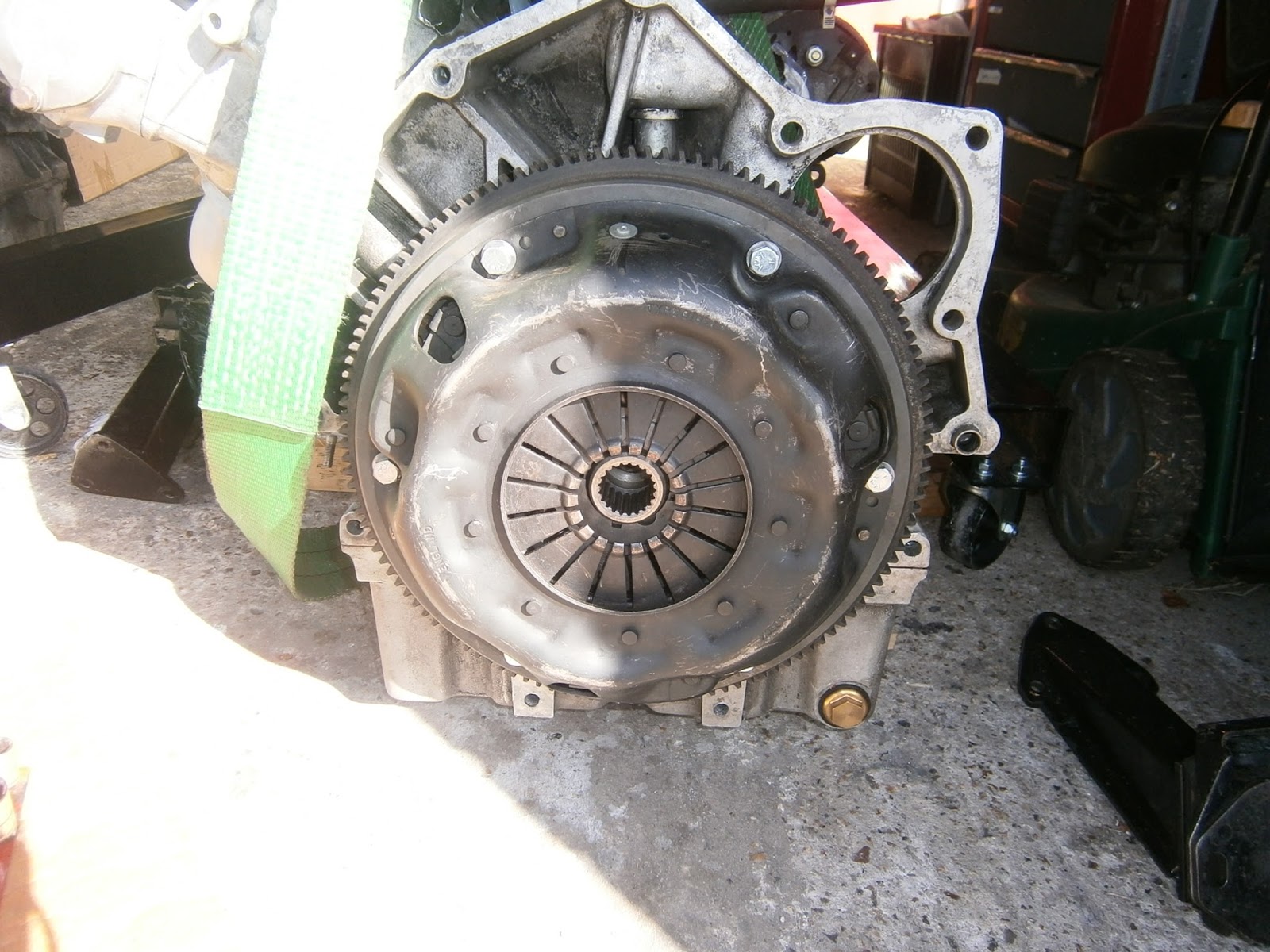
I removed the latch- fairly easy just 4 Allen head machine screws, the short one goes at the bottom towards the inside of the car. There is a spacer between the latch and door frame through which the upper two bolts pass. To maintain position there are round spacers on each of the two lower bolts. The latch mechanism could then be finageled out- but its awkward with the projecting rods. Once the latch was out I took a few views in case I couldn't get it back together. Sorry about the focus in these- the camera couldn't cope with the combination of light and distance- plus its not working too well.
 |
| Side view striker plate towards the hand, plastic centre section and rear wing of interior handle lock -and-open plate. The cross link rod is visible end on, in a small slot at the top of the side plate |
 |
| Rear view of latch inner handle plate wing to left and covering the rear of the latch, external key and handle plate to right. Large retaining rivet in centre with centre mounting bolt hole above. |
 |
| Key lock plate with "Z" cutout for door handle operation, straight cutout for key locking operation. |
 |
| outside view key lock plate... note Z cut slot and straight slot. |
 |
| Rear of lock with fixed rivet |
 |
| Front of latch striker plate with small rivet top |
Inspection of the latch showed two obvious problems:
Firstly, when I had tried to fix it before I had replaced some of the rod attachment sliding washers. At least one of these (on the Z plate) was too small and allowed the rods to get jammed in the cutout. It was also too thick so the C clip couldn't enter its groove and kept sliding off. I found a larger and thinner washer and refitted this making sure that the rods could still move over their entire range and that the C clip now sat squarely in the groove. The new washer was sufficiently large that there was now no way the rod could twist or slip out and jam in the Z plate.
 |
| New washer installed on Z plate exterior handle rod |
The manual says to adjust the lock barrel rod length so that turning the key from lock to unlock positions causes the rod to travel the full length of the straight slot. This was never possible. In fact it seemed that the rod wouldn't move the full length of the straight slot anyway- even when the lock barrel was disconnected! It looked like the latch would need closer examination so time to delve deeper I think... Inspection showed that the rear plate covering the lock (ie the foot of the internal handle plate) was sightly loose. Further the key plate seemed to slide up and down in a haphazard manner causing the key rod to jam in the straight slot. It all seemed far too loose and disorganised. It seemed to me that there was a problem inside.
The latch isn't I think a service item- its not meant to come apart but in order to open it I supported the latch on a thinnish piece of wood placed under the large rivet head...
and drilled out the small rivet
This pushed downwards a little
and could be removed from the rear carefully holding everything together- I have been warned about spring loaded internals!
This allowed the larger of the rear plates serving the internal handle to be lifted up releasing the linking rod beneath
 |
| Having removed the rivet the back plate (internal door latch plate) is loose. Note the linking rod at the top of the latch is located in the inner latch plate and passes under the back plate part. It is being released here as the back plate is raised. |
 |
| ...and can be removed |
Internal lock plate removed, Key locking plate and linking rod still in position.
The key locking plate has a small footprint on the back of the latch, but this contains a hole which ought to locate over a stud that penetrates through the plastic latch body. It wasn't on this stud but sliding up and over it although it could be slipped backwards to engage the stud if it was held firmly in place. Once located on the stud the movement of this plate changed completely- it was now firmly mounted and slid easily up and down, returning under spring action to its starting point and controlling the pivoting action of the wing. This seemed to me to explain the problem in movement I had observed earlier and the jamming of the barrel lock rod in its groove.
 |
| Removing the interior handle rod plate (top of picture) Note the small cutout in the bottom of one of the moving pieces. When in position this slips into the groove visible at the top of the latch body below the linking rod. This mystifies me as there is nothing obvious for this cutout to locate over and I do worry that something might be missing/broken in the latch body. The key lock plate "foot" is visible at the bottom of the picture- note that there is nothing visible in the hole in the foot where the locating peg should be. |
 |
| Sliding the plate backwards and applying pressure caused it to pop into position on the stud. |
 |
| Stud (key locking plate removed) |
I removed the key lock plate and examined its foot- there were clear indications of how it has been sitting over the stud rather than on it- and when viewed from the side the foot appeared slightly bent thus raising it above the stud and allowing it to slip over it. It also accounted for the distortion and looseness between the latch body and the back plates and I believe explains why the lock stopped working when the latch was screwed tightly to the door. This would compress the back of the latch, squashing the foot of the internal handle plate onto the foot of the external handle plate, immobilising it on top of the stud, preventing it from sliding and thus jamming the lock.
 |
| Foot of key locking plate. Note telltales showing that this foot has rested on and over the locating peg rather than on it. |
 |
| Foot viewed side on- the rhs in this view is bent slightly upwards preventing the foot from lying flat in its groove. |
I bent the foot flat in the vice and refitted it- this seemed very successful, it fitted onto the pin and the covering plates could now lay flat in position on the latch body.
Turning the latch body over revealed the multiplicity of metal components and the spring loading mechanism that should keep the lock plate in the correct position.
 |
| latch components behind the striker plate. A spring loaded plunger (top) presses down on a hooked ratchet arm. This is then pressed against the rotating latch disc. When dismantled the hook wasn't engaged in either of the rotating disc retention slots but I assume this is rotated by the door striker when the door is shut to engage the latch. There is also a spring strip across the top of the latch- removed in this pic but visible in that below. The hooked ratchet arm bears a cylindrical pin which is visible below the spring plunger. This pin penetrates through the plastic body to engage with the barrel lock plate slider on the rear. |
It was at this point that the inevitable happened and the rear components went "ping" and detached from the latch body. Luckily I had photographs and could reassemble, although reinstalling the central rotating latch plate was tricky as it wasn't immediately clear where this should locate. I think it is meant to slide between the two round cutouts formed by the latch's plastic body an the spring clip underneath the disc.
 |
| Spring loaded plunger removed, rotating latch plate still in position. |
 |
| Rotating latch removed showing the spring clip beneath. The peg on the back of the disc fits into one of the two locating mouldings formed between the spring clip and the latch body shown centrally in this pic. In my case this fitted the lhs mounting point. |
I was able to reassemble the latch, however closing it now that the rivet was destroyed was a problem. I held it temporarily with an M5 nut and bolt whilst i found a better way.
Thinking about this- the original rivet was 0.25 inch in diameter. the latch fixing screws are 1/4 UNF... 0.25 " in diameter. I can therefore replace the rivet with a 1/4 UNF nut and bolt... then considering a little bit more, there is no space for a nut on the rear of the lock... but there is a large spacer here already so if I drill this out (5.5mm) and tap to 1/4 UNF then the spacer itself will become the nut! It is necessary to widen the rivet hole through the striker plate at the front though as this is currently too small for a 1/4 " bolt. I gather from the forum that there is sufficient room for a nut on the outside of the striker plate without fouling the door.
 |
| I marked the position of the rivet hole on the spacer plate and drilled it through with a 5.5mm bit |
 |
| This could then be tapped to 1/4 UNF |
 |
| The striker plate hole was quite small so I drilled this out with a 1/4" bit taking care not to damage the pivot sections beneath. I checked that the bolt would slip through easily. |
 |
| The bolt then threaded into the spacer leaving a few mm protruding. I removed it and ground it to length so that it terminated flush with the rear surface of the spacer plate and retains the latch contents. |
The only problem with this solution is that the spacer appears to be aluminium not steel and so probably not strong enough for threading - although it only needs to hold the lock together whilst it is off the door as once fixed to the door the 4 mounting screws should hold it firmly- and these are screwed into steel. I don't really like a nut protruding from the striker plate either so as a final iteration, I can order some 5 mm steel plate (5cm square required) from which to cut a stronger replicate spacer. Further, the striker itself is thick enough to take a countersink (as the latch mounting screws are already countersunk in this plate) so I will order a few 1/4 UNF flat head countersunk machine screws 3/4" long and this should fit nice and flush at the front. In the meantime I can assess the suitability of my "fix" using the aluminium spacer plate and 1/4" bolt once the external handle is sorted.
When reassembing the latch it can be tricky to work out how the various pivotting plates should be positioned- I took a few pictures of these in the correct position on another latch which could help.
 |
| Note cross link engages with slotted cutout on the inside, the crescent plate is free as shown with the notched end downwards pointing towards the plastic body. |
 |
| Z plate- lock tab is at the bottom of the right hand lever and slips into the space above the footplate slider when the door is closed. It will not lock while the door is in the open configuration. |
 |
| This plate has a weld repair to hold the pin but does not stop the pivoting on this pin. |
Exterior handle
The exterior handle was easily removed by unscrewing the two mounting bolts- in this case one remains at the rear and a new one was fitted to the front where the plastic mounting point had been damaged (and was replaced with a drilled through nut as explained in an earlier post).
 |
| Rear of exterior handle, mounting points at left and right. The LHS point is damaged and has been drilled through to fit a mounting bolt. Mounting plates removed and not shown. Barrel (left) pivot to left and exterior handle to right. |
There was a considerable amount of slack wasted movement in the key operation before the key pivot was moved. This was attributed to wear in the pivot. The key pivot arm (LHS above) is retained on the barrel lock shaft by a spring circlip and can be lifted off when this is removed.The shaft onto which this fits has a "half moon" section which should locate into a "half moon" cutout on the pivotting arm.
 |
| Key pivot arm- Half-moon cutout to fit onto arm- note wear to RHS which has eroded the rhs locating ridge upwards and app 1mm above that on the left. |
I infilled the worn areas with a blob of weld and then filed/ground this down so that the profile of the locating ridge was restored in a lower position and the pivot arm now fitted over the barrel with no significant dead movement when the key was turned.
Refitting latch and exterior handle
Having completed the latch I refitted it making sure that the rods protruded through the correct cutouts in the door and door beam. By pulling on the rods I was able to test their function alone (i.e. not using the handles). This showed that all functions worked... but fitting the rods onto the handles and maintaining function was far from simple. I would like to say that there is a simple and logical way to adjust the rods... but there isn't! There is a system in the manual but its not feasible to follow it and access is poor meaning that its hard to judge the position of the rods in the slotted plates (often even which rod is which!) and its not possible to adjust their lengths in position. Note to Lotus- why not put an adjuster in the middle of the rods so you don't have to keep loosening or removing the exterior door handle assembly, adjusting the rods, refitting and testing. I eventually got all functions to work through the handles but it was largely trial and error- basically I made sure the lock was unlocked and then adjusted the external handle rod to sit in the position shown in the manual (left end of horizontal slot) and just reach its locating hole in the handle without moving it. I then adjusted the key barrel rod to fit into the barrel arm when its at rest without strain; this left the barrel lock rod app half way along its slot. Finally I adjusted the interior handle rods which was much easier: At last I have a functioning lock!
Door Trim Panel
I went ahead and refitted the door trim- making repairs as necessary. The door trim panel just seems to hook over the inside of the door and the overlap contains the lower window wipe-seal or weather strip which then fits against the glass. The trim itself is then retained with 2 screws underneath at the bottom. The panel did refit but I found that the glass wipe seal strip wasnt a good fit at the mirror end- infact the trim doesnt seem to clip over the door very well at this end at all: There is a large gap, certainly large enough to get a finger in!
 |
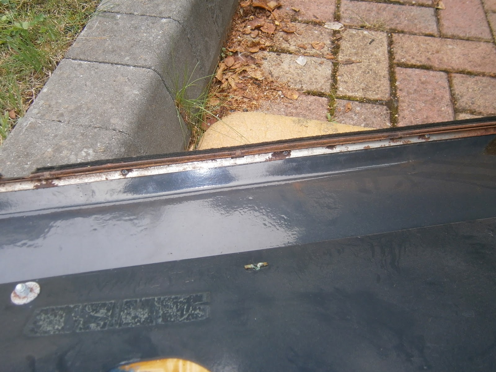
| Glass wipe-seal strip- fits nicely against the window on the left but there is a clear gap on the right as it passes the inside of the mirror mounting. |
 |
| Finger to emphasize gap |
I'm not sure at present whether this is simply because the wipeseal needs changing- it is quite rusty, but as its held on with pop rivets the rivet heads themselves may be stopping the trim panel from slipping over the edge of the door. There are some clips inside but all are horizontal and look more like rests than clips to grip the door edge. The Driver's door is the same so this may simply be as expected? I note that Lotus do list some draft excluding foam to be used "as required"- which sort of suggests that gaps aren't always unusual? Intrinsically though it doesn't look right and I think I will need to try removing the mirror and re-addressing this issue.
OK well good news and bad news- turned out the passenger's door was an easy fix. You simply need to remove the mirror stalk trim and fit the door trim panel first- refit the mirror trim afterwards.
I removed the door trim again to try and work out how its fitted.
 |
| The door trim has a folded metal strip pop riveted to its upper edge. Its this strip which is meant to clip/hang over the edge of the door's inner leaf. There is a wipeseal/weatherstrip element clipped to this metal edge so-formed. This means when the metal is hooked over the inner door skin, the wipe-seal should be against the glass. |
 |
| Metal strip on edge of door- pop-rivets visible underneath. |
 |
| The blanking plug in the mirror fitment holds the trim on- its just a press fit in the mirror stem and can be levered out carefully with care not to damage the mirror corner trim |
When the trim was off the nut underneath seemed pretty rusty- Itr also penetrates through the glass so I didn't want to monkey with it. Note that the top of this door's inner skin has little half moon scallops molded into it which correspond to the positions of the pop rivets holding the edging metal onto the trim panel.
 |
| Corner trim- button in position |
 |
| I was worried that so much rust came out from under the trim. Note that the top of the inner leaf of this door has little scalloped depressions moulded into it that correspond to the positions of the pop rivets holding the metal edging to the trim panel |
 |
| ...so I cleaned the mounting nut up and treated with jenolite. This nut penetrates through the glass and I doubt can be removed without breaking the window!- this was a risk I wasn't prepared to take. I don't understand why but the top of the door is covered in duct tape- but some was missing so I replaced it with new |
 |
| Refitted the door and got a lovely smooth and close fit- meaning that all that was left was to... |
 |
| Refit the mirror trim. I put a little grease on the trim button so that it could be removed more easily in future. |
The driver's door had a similar problem- and I expected a similar fix- in fact this didn't go as hoped.
 |
| I had forgotten about the various switch connections to this door panel- pic to make sure I reconnected them right! |
 |
| The multiplug was damaged and as a result it was loose. The rivet had pulle dout distorting the cap |
 |
| It pressed back in with a little superglue to restore fit. I applied dielectric grease to all contacts as is now my standard practice. |
I suspect strongly that this door has been changed at some point and this may be the source of the problems on this side. I removed the mirror trim and repaired the tape on the top of the door's inner skin as before- but whatever I did I just couldn't get the wipeseal to sit against the glass- there was always a gap.
There were two differences I noticed with this door- firstly the top of the inner leaflet was much more curved over which meant that the hanging strip of metal on the door trim panel couldn't really clip over it. Secondly the top of the door wasn't molded for the pop rivets and these were leaving telltales where they were being forced against the tape. Both of these effects presumably combining to stop the trim sitting back against the glass.
 |
| Telltales in the tape where the pop rivets are mashing up against the door inner leaf. One indicated and another on LHS. |
I used a Dremmel to grind out some scallops to accommodate the pop rivet heads and this helped a lot. However it didn't solve the problem and although I now have a straight and even weatherstrip/wipeseal line, there is still a gap between the seal and the glass. This I attribute to the shape of the door inner skin which leaves the trim farther from the glass. This is a case I think where some form of spacer (foam strip) as mentioned in the Lotus parts for use " as required"... is required.
 |
| Drilling grooves for the rivet heads has helped a lot- the strip of seal is now straight and even - and much closer, but sadly there is still a gap between the glass and seal strip. |
I will leave this to a later date. My motor is now apparently ready so I'm going down to collect it tomorrow- and this means that I now have bigger fish to fry!