Yes folks- I managed it alone and finally the motor is where it should be. I'd like to say it was done with ease, using surgical precision; but that would be a lie... it was really quite brutal and involved a lot of pushing, pulling, heaving and re-jacking but eventually everything lined up. Here are a few notes about how I did it this time...
Before fitting the motor I took advantage of the access to refit the camcovers in the right positions and the right way up- thank you forum!

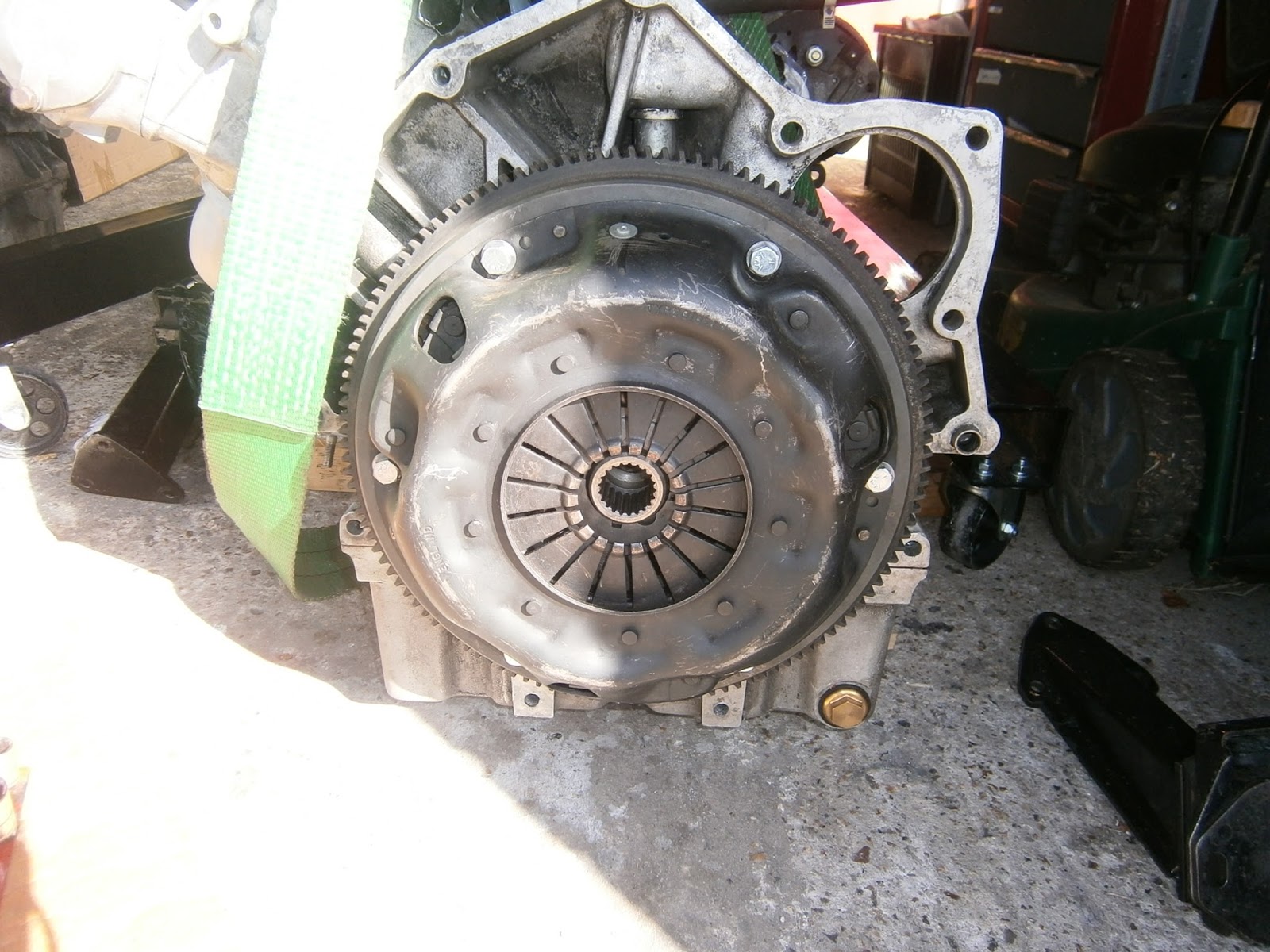
I had already fitted a new spigot or pilot bearing. I was able to tap this in to the 0.9 cm depth expected. I used loctite to keep it there. I also refitted the flywheel and clutch...
... and the PAS pump, alternator and associated belts. I also re- tensioned the cambelt as this had only been done roughly before sending the motor away.

I also refitted the left hand motor support leg below the exhaust manifold as access to this one is really tricky once the motor is in. However I took the foot off and fitted that loosely to the chassis so that I could (hopefully) feed the motor over the mounting stud as it is lowered into position.
I used the guide studs again- these certainly help and in my view fitting a motor single-handed without them is just about impossible. I used 3 at the top but I think another one or two at the bottom would help.
 |
| Three guide studs in position, top mounting tapped at M10 right through |
 |
| Screw slot cut in the end of the guide studs. |
I wanted to fit the 20 thou shims apparently required by this sump but these were a bit of a problem as they didn't slip far enough up between the mounting flanges to engage with the lower mounting bolts as you pushed them through. Even a magnet didn't help, but eventually I was able to position these using little masking tape handles to insert and position them between the cases.
 |
| Masking tape handle on 20 thou shim. |
 |
| Sump-bell house join bolted up snugly and a vast improvement on my attempts before modifying the crank. |
 |
| RHS of motor/bell house join- in fact I did have to remove the slave cylinder to gain access to the two mounting bolts in this area but this was relatively straightforward. It was these two bolts which effectively pulled the two parts together and aligned the motor properly. Pretty important ones I feel! |
 |
| Motor in position... the workings of my strop re the positions of the bell house and mounting legs means that I will need to cut it to remove it... shame but I think a small price to pay for a job now completed! I have also torn the Hardura insulation on the bulkhead (Note to self- watch the ends of those alignment studs as you lower!) so I will have to find some neat way of covering that. |
The motor and bell house fit together with 9 M10 bolts of differing lengths. I couldn't find anywhere a description of what-bolt-goes-where: the parts list doesn't show this and as my motor had most of them missing I'd had no guide from disassembly. However I measured the depths of the holes and the best guess I can come up with is below.
 |
| Bell housing bolt lengths in mm. Note that "sm" are starter motor mountings and "nb" is a nut and bolt. The 55mm bots fit through the locating pegs at these points. |
So there we are- motor finally in... of course there is a long way between here, refitting the ancillaries and getting everything working, but at least I'm off on track again!
No comments:
Post a Comment
Feel free to let me know what you think of this blog. I'm working on my own here so any feedback from those Lotus enthusiasts floating around "Blogger Bank" is welcome. Suggestions for process improvements especially welcome. If you like it please follow.