As I have already ordered new hoses- or thoroughly cleaned those that are still serviceable (most needed de-rust treatment as there were crunchy rust deposits inside); this just about completes my cooling system overhaul. The only bit I haven't dealt with is the heater. At this stage I expected the only problem to be a blocked or corroded matrix; I expected it to be as clogged as the radiator! However it now seems that there is rather more to this seemingly simple piece of auto equipment (see below!).
All accounts state that the heater is very (very!) hard to access. If you don't believe me check out Edd China's work with an Esprit in Wheeler Dealers or Stoneyexcel's excellent blog which shows clearly the nightmare that lurks behind every Excel dashboard!
This means that I am only after simple fixes here. I will do what can be done without attempting to remove the dash and this includes a reverse flush to clear what is likely to move and check that there are no leaks into the cabin. I may try filling it with Deox C to see if this can shift a little more sediment but if its like the rad I expect a replacement is really needed. Athough a heater is nice to keep warm and demist etc., its not absolutely essential in order to run the motor so it isn't a problem I absolutely must solve now. One thing though is that I have been told that running with an obstructed heater restricts fluid flow from the rear of the head. This in turn can cause poor coolant flow around, and overheating on, no 4 cylinder. If I can't fix it I will need to bypass it so that coolant can still flow from the motor through those pipe exits from the head.
First step: I set about flushing the matrix.
Flushing the heater matrix.
A wet and unpleasant job. I checked that the heater control moved the lever on the valve and that didn't appear to be jammed. Good news then. I then attached a hose to the heater outlet pipe ...
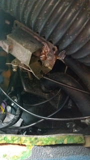 |
| Water control valve (galvanised box structure) viewed from driver's footwell |
...but there was absolutely no flow through the heater! Switching pipes didn't help either! No flow in either direction. I was definitely not going to strip the matrix out so I resorted to raising each hose in turn ... filling it with water and then dipping it downwards to siphon/drain. Each time this brought a little sediment out at the end of the drain until to my amazement it suddenly flushed through discharging a load of rusty water on the drive. I kept forward and reverse flushing it until it ran clear. Finally I tied the hoses up vertically and left the matrix filled with 10% citric acid (descaler) overnight.
A comprehensive final flush the next day displaced some now very darkly coloured descaler and shifted a lot more brown gunk.
During flushing I did find that there was a slight drip into the drivers footwell. I wasn't able to find where this was coming from - it may not be the heater itself as there was quite a lot of water flying about during this process but I was always intending to carry out the initial fill with Barrsleaks or Radweld, and then replace it for the correct coolant after a good run up to operating temperature. This should fix any slight leaks as in the heater, but also its a safeguard in case the cylinder liners aren't sealed absolutely watertight in the block- I think they are but this is simply insurance.
 |
| Heater hoses tied up so that the matrix could be filled with citric acid solution. |
Progress
As a tutor I once reviewed GCSE experimental scripts-- all began with the immortal words "What we done was..." so in the best spirit what is currently GCSE results week...
"What I done was" firstly to replace the hose joiner in the heater-to-rad hose under the bonnet- here is the old one nasty and corroded. I invested in a new aluminium joint. I got two of these but the other join is hidden so wont be changed unless (Heaven forbid) I end up stripping the dash.
 |
| Hose joiners old and new. |
During the radiator refit I had also found some coiled wires and a surprise tube (with what looks like an in-line brass valve) under the top of the nose (i.e. in front of the radiator).
 |
| Hose emerging from LHS headlight pod via a brass valve-like structure. It doesn't go anywhere and its end is open. Note cabling behind the hose. All firmly clipped to the front of the nose. |
These were both a mystery to me: I don't know/can't remember whether I tied up the wires with a cable tie when I stripped the rad, or if they were unused and just like that from Lotus. I freed them now in case I need to connect them as it will be easier to hide them again if they aren't used, rather than retrieve them after the radiator is fitted if I find they are needed!
The hose was more interesting... I didn't know what it was! The hose runs through the LHS headlight pod and disappears into the void above the wheel arch, heading for the passenger side of the dashboard, but I would need to remove trim to see where it emerges inside the car. It is clearly not being used in the case of my car since the LBPO disconnected it.
 |
| Pre '86 heater air control fittings; flaps direct the air through vents and vacuum valves control the operation of those flaps. |
However it seems that it should connect to the short blocked-off stub I found emerging from the front of the intake manifold when I stripped the car. This connects intake manifold vacuum through a non-return valve (the brass structure I had identified earlier) into the LHS headlight pod and from there it disappears into the bodywork to emerge as a narrow bore pipe at the heater above the passenger's feet. This connects to a vacuum reservoir beside the heater. This arrangement of reservoir and non-return valve holds vacuum in the system as engine speed (and thus manifold pressure) varies. From the reservoir hose, a second pipe emerges and immediately splits into 2 at a Tee piece. Each arm then feeds a separate valve located somewhere behind the dash and operated mechanically via the heater direction control knob. When opened, these valves then feed vacuum via further narrow hoses to two vacuum operated motors... (basically capsules containing a spring loaded diaphragm connected to a lever). The vacuum pulls on the diaphragms thus moving the levers to push or pull the heater flaps and so direct airflow. Without vacuum the flaps cannot be moved- although I think they can both be left in a fixed position which obviously allows some heater function.
There is a clear problem with this system- obviously it needs to be airtight or it will leak air and the inlet manifold will be trying to evacuate the universe in general! This will introduce excess air into the manifold, weakening the fuel/air mixture and upsetting the running. The system consists of a large number of hoses of different diameters and a multiplicity of rubber joining pieces, elbows and adapters all of which can perish and split- let alone just fall off! Any such problems will create an air leak. Given the very real difficulties of access to repair anything behind the dashboard I am assuming that such leaks explain why the system was disconnected in my car and the connection to the manifold blocked to preserve engine vacuum.
I started to investigate the control system by removing the non-return valve. This has a length of stiff PVC pipe on each end which seems to be a simple push fit onto the small bore hose used to pipe vacuum around the heater system. These sections were very stiff and I doubt will give a good seal so I will probably replace them. The valve wouldn't let me blow through in either direction although I think this is simply spring pressure. These valves cost in excess of £50 (although I think it can be replaced with much cheaper plastic versions) so I thought at the very least I should clean it and check operation.
The non return valve unscrews both ends with a 3/16 WW spanner. Inside there is a spring loaded piston, the pin end points towards the manifold and the piston end towards the heater. The piston did seem to be a little sticky but it depressed easily enough with a gentle push. I held it open and blew through it to clear it, and reassembled the valve.
 |
| Non return valve- stiff old hosing attached. Inlet manifold direction to left |
 |
| Manifold side of NR valve |
 |
| Heater side NR valve |
The ends had been sealed with a crumbly white sealant (resembles plumbers jointing compound) which had obviously dried out. I cleaned all this off and resealed the valve using Loctite thread sealant 243.

I could still not blow through the assembled valve though.
Finally I reconnected the valve to the narrow bore hose in the headlight and applied a vacuum via my hand pump.
 |
| Hand vac pump (brake bleeding pump) in use |
 |
| Vac elbow connecting to motor (right) from reservoir (left). Actuating arm vertical right. |
Checking under the dash at least part of the system was visible. From the passengers foot well I could see the vacuum reservoir (brown metal drum) and hose/elbow connecting to the 1st vacuum motor (brassy capsule on right). This elbow is split and will be replaced. I couldn't find the second vac motor and wasn't able to inspect the other rubber pipe unions/elbows and adapters. The actuating rod in this view leaves towards the top right of the picture to connect with...
 |
| Actuating arm enters from left attached to short flap actuating lever. |
... the outer vent operating flaps via this hinged arm (enters from LHS in this picture). This was a little rusty so I sprayed it with the maintenance oil.
I evacuated the system again using my hand pump and then operated the heater direction control- the arm moved in a very satisfying manner and once more I couldn't detect any hissing leaks- although these may only be apparent at greater vacuum. |
| View from driver's footwell. Galvanised box is the water control valve. One of the vac control valves is just visible in the centre of the picture- very hard to see here but clearer in endoscope pictures below.. |
Using my endoscope I was able to check the rubber elbow connections to this vertically mounted valve
 |
| Vertical valve- note elbow entering from above and a second connected at the bottom of the picture |
 |
| Adjusting the vent direction control showed that the valve piston moved |
 |
| Heater controls pre 86- air control panel and arrangement of the vacuum valves it operates. |
 |
| Horizontally mounted valve- 1 elbow attached from thew bottom (rhs) of the picture but the second should be attached to the outlet that can be seen penetrating the metal plate in the centre above the valve. I couldn't see that to check. |
 |
| Operating the air control did indeed move the valve piston... visible extreme left. |
My plan is thus to reinstall the motor and attempt to get it working after connecting the heater coolant hoses but without connecting the heater vacuum lines. I will do this if and when the motor is running satisfactorily.
No comments:
Post a Comment
Feel free to let me know what you think of this blog. I'm working on my own here so any feedback from those Lotus enthusiasts floating around "Blogger Bank" is welcome. Suggestions for process improvements especially welcome. If you like it please follow.