I bought the Dellorto rebuild kit from Eurocarb- kit containing 170 size needle/ valve. Their service was amazing with delivery within 24 hrs. The kit itself was a little disappointing- mainly because it didn't include the needle valve filter or the Dowty washer for the fuel union. The latter is probably forgivable as this seems to be peculiar to Lotus, but the valve filter must be a Dellorto part. Also, I felt that the fibre washers were a little flimsy and insubstantial compared to those already fitted and 2 of the gaskets had been changed to paper rather than the black nitrile-like stuff that was present originally. None-the-less it contained the most important parts needed- plus I think a few more and this did raise a little confusion.
The contents of the kit (one carb's worth) are shown below sorted out to put the similar parts together.
 |
| Contents of Dellorto DHLA45 rebuild kit (1 carb- kit actually contains parts for 2) |
I have tried to list what goes where (as I see it): Top left are the fibre washers and filter for the banjo union- not needed in the Excel, then come the 3 carburettor body gaskets (fitting obvious) and a variety of washers.
There are 2x 12mm fibre washers (base of Acceleration pump jet). 1x 12.9 mm Aluminium washer (base of needle valve filter holder); 3x 8mm (1.75 mm section) nitrile O rings (2 for the idle jets and 1 for the pump non return valve); 1x 8mm (1.75mm section) nitrile O ring (not needed?); 2x 6 mm (1.75mm section) nitrile O rings (top of acceleration pump jets); 2x 5.4 mm (1.5mm section) nitrile O rings (Idle mixture screws? or not needed).
Then there is a replacement diaphragm and spring for the acceleration pump, a new (170) needle valve unit (in plastic box) and a new pump arm return spring.
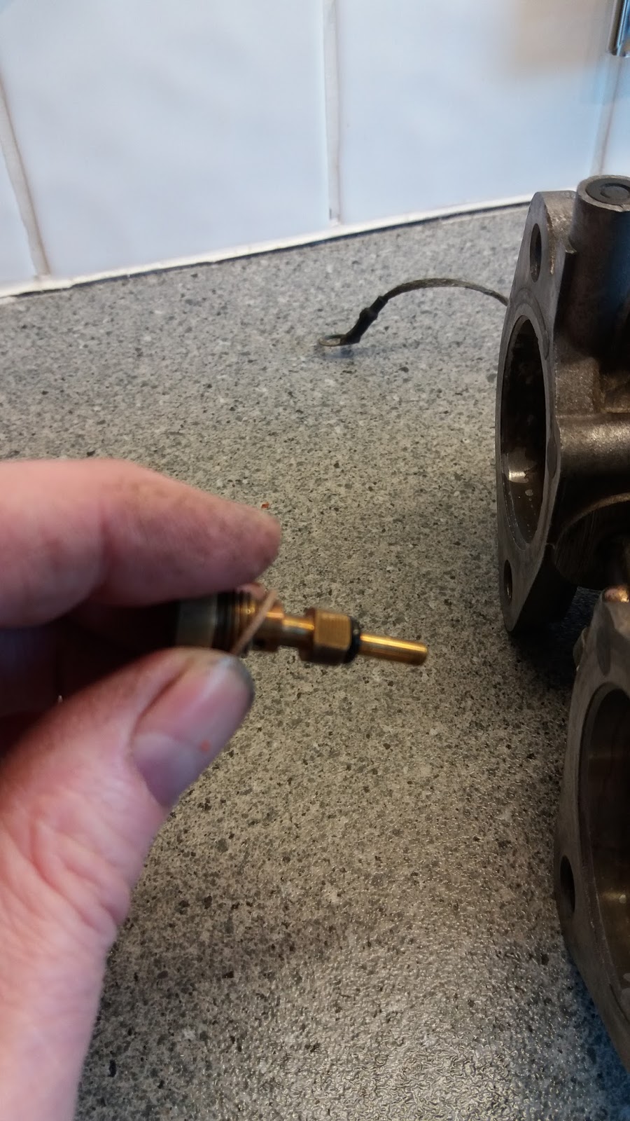
As I said above the Dowty washer for the fuel inlet was not included. This presented a bit of a problem as its not immediately apparent what size is needed. The union (shown below) is threaded at 20 tpi on both sides. However one side is 0.5 inch diameter and the other 0.47inch. I think the 0.5 section (i.e the side that screws into the carb body) is actually an M12 fine, but I can't identify the other side which is as close as I can see a BSC fitting! However the Dowty fits on the 0.5 inch side so an M12 (or probably also a 1/4 BSP) bonded washer should fit. I have ordered a few- they are very cheap and for £69 could perhaps have been included in the kit!
 |
| Fuel union fitting- Bonded washer on 0.5 inch thread. |
I finished sonicating and cleaning all the components of the first carb and sorted them for assembly. All components are screwed in tight except the mixture screws which I haven't removed. I did check that both are clear and I will adjust them on the car... if and when I get it running! I don't want to remove the anti tamper plugs until I am ready to do this- I have got new ones also from Eurocarb.
A few other points... the acceleration jet has a flat on one side... if you look carefully there is a matching flat in its socket which means it will only fit one way round... with the outlet hole pointing towards the motor.
 |
| Flat on acceleration jet |
 |
| Matching flat visible inside acceleration jet mounting hole (lower centre) on the right of the hole... zoom in for clarity. |
To fit the acceleration pump mount the spring on the diaphragm centre boss. Line it up on the pump top and lower into position.
The throttle needs to be held open to allow the acceleration pump to descend in a flat even manner across the carb so the diaphragm can be aligned and the screws can be tightened.
Float chamber cover gasket must be fitted before the float- don't forget to insert the needle into the float before fitting! I fitted the original needle valve filter to the new valve seat as there was no replacement included in the kit.
As before fit the float pin from the solid support side tapping it towards the split support. Once fitted, I checked the float height to the gasket measured at the base of the float (narrowest point)- the gap was 12mm|* as specified. I also checked the droop distance and this was as specified 27mm as well. Overall no adjustment needed on this carb.
 |
| Setting float height 15mm at lowest point of float to gasket surface. |
* Ah well- it pays to read and remember the book better! This should have been 15mm by Mr Hamill's reckoning, so I was setting the float too close to the carb top- ie too high; and it will permit too high a fuel level if set like this- I had a lot of overflow/fuel drip problems later on when I finally got the motor to run. I will post an entry with more about about float heights and fuel levels later on- if I ever solve the problem that is!
The rest of the rebuild really went as expected so I'm not going to present any pics- safe to say the first carb is complete- I have one more to do and the moment of truth approaches!
I then rebuilt the second carb before fitting them both onto the inlet manifold. Although I do have one already prepared, this has a different layout for the coolant connections so I will refit the original manifold.
The old manifold needed to have the spacer mountings removed.
 |
| spacer in position- flattened O ring on top... |
 |
| ... and beneath |
 |
| Removed spacers before cleaning |
These were quite tight but tapped out and I cleaned the spacers in the sonicator and polished the conical recess sections. The point of the cone goes towards the motor and helps to prevent reversion of gases from the manifold into the carburettor.
 |
| Cleaned units- new O rings for the spacers were included with the head gasket set. |
 |
| Clean up manifold surface then assemble ring to the conical side and insert cone side down for anti-reversion effect. |
 |
| spacers fitted |
I then inserted a second o ring into the top of the spacers before aligning the carbs at the slip link and offering the pair up to the manifold- they slipped on easily.
 |
| Refurbed carbs in position on inlet manifold. |
 |
| Slip linkage |
The carbs are bolted down using the spacer rubber washer/cap washer system The cap washer goes on first but those fitting to the lower studs has a flat facet to fit under the bulge of the carb.
 |
| flat facet (top) on lower cup washers. |
The rubber washers then slip on followed by the second cup washer and finally the captive nut. I tightened these down evenly trying to get an even 1mm gap around the carb and spacer and between spacer and manifold. The idea here is not to tighten the carbs down firmly since this would ruin the shock-absorbing function of the spacers.
 |
| Tightening the carbs- I used a strip of aluminium 0.9mm to judge the gap. Its necessary to alternate between top and bottom gaps until both are right.- Use 2 hands- I have to use one to hold the camera! |
 |
| Carbs installed |
 |
| Manifold and carbs from above: Much cleaner! |
Once the carbs were on the manifold I checked that the throttles opened evenly. To do this I removed the progression hole covers and placed a lamp behind the manifold blocking off direct light. I could then fix the throttles in a set position with a screwdriver and check that the progression holes were evenly exposed.
 |
| Throttles jammed with screwdriver and inspection light positioned above manifold openings. |
I could then look through the progression holes from barrels 2 and 3 to judge the position of the butterfly. The linkage screw can then be tweaked to set them at the same point. Finally the screwdriver was removed and I checked for even sweep of the butterflies across the holes as the throttle was moved. Only a small adjustment was necessary.
 |
| butterfly position revealed by light through the progression holes |
 |
| Butterflies slightly out but corrected via linkage screw. |
I could then fit the manifold to the motor- new gasket of course. In fact the last remaining gasket from my top and bottom end sets!! Very satisfyfing to use it! I cut the manifold to pump water hose to length carefully so that it would fit well onto the water pump and manifold. I fitted it to the pump first using marine protection grease to make sure it slipped on easily.
Loading the jubilee clips onto the hose and then insert the manifold by sliding it into the hose and pushing it back onto the studs.
The clips can then be tightened- access not great but possible. The rearmost clip could be reached through the gap between the manifold throats.
water pump screw- access no problem!
There are earthing connections from manifold to thermostat cover and from rear card to manifold nut. I connected the choke cable and link using the nut I had made to replace the missing fitting and fitted the throttle cable.
Finally I reattached the belt guard and clipped the throttle cable into the guide on the guard.
I still need to insert the plugs but I want to spin the motor a bit first to spread oil; I filled the motor with 6l 20/50 mineral oil and added water to the reservoir allowing it to sink down. I added PAS fluid to the pump reservoir and jacked up the front of the car to turn from lock to lock to spread it before topping it up again. Finally I could spin the motor on the starter and then top up the water and PAS fluid again
I had anticipated getting detectable oil pressure just by spinning the motor, but since this was completely dry, I think this might not be possible straight away. The motor is now pretty much complete and back in- sadly at the moment although it looks really good its pretty much an ornament until I can try to start it and I'd like to find some way of checking that the oil is being circulated before I do that.


No comments:
Post a Comment
Feel free to let me know what you think of this blog. I'm working on my own here so any feedback from those Lotus enthusiasts floating around "Blogger Bank" is welcome. Suggestions for process improvements especially welcome. If you like it please follow.