Enrichment device:
The enrichment device (or choke in UK parlance) is contained partly in the lid of the carb (control mechanism) and the body (fuel/air passages). It is held to fail so rarely that servicing it isn't really described well anywhere. I have lifted these diagrams from the Laverda club but the description is mine.
 |
| Overview of carbs, enrichment device control is located in the towers visible on the lids and capped with a large brass hex plug. |
The official Dellorto exploded diagram is below...
 |
| Dellorto diagram- exploded view DHLA 45. Choke control mechanism shown top left and the tower piston top centre. |
Choke in operation.
The choke operating system in the carb top consists of a rotating lever/cam which raises or lowers a piston contained in the tower. Operating the choke control pulls on the lever (39) which rotates the eccentric pegged shaft into a groove in the choke piston (18) contained in the tower, raising it against the pressure of the spring (19). This piston is very similar to the piston contained in an ordinary ball valve; it has fixed into its lower end a blank rubber (nitrile?) washer. When the choke is closed this washer is held by spring pressure against the choke diffuser (116, but not indicated in this diagram) opening in the lower carb body preventing air from entering, when the piston is raised as above, the washer is raised allowing access to the diffuser.
The effect of raising the choke is shown below using a diagram from the Laverda club. The piston (7) is raised and fuel is drawn directly from the float chamber through the starter jet (12) and its associated emulsion tube where it is mixed with air at a richer than normal ratio. The mixture passes into the choke diffuser at (8) which splits it into two streams. These pass down separate passageways (9) to exit in the throat behind the butterfly. This provides a direct and low resistance path for a richer mix to enter the throats behind the throttle butterfly (10).
 |
| Laverda club DHLA45 diagram of choke in operation. Fuel from the float chamber (shaded) is drawn up through the starter jet (12) and emulsion tube (11). It is mixed with air and this mixture can enter the choke diffuser (8) and associated passageways eventually to exit behind the butterfly at (10) |

Should you need to change the washer though then its not straightforward as I can't find this washer listed separately as a replacement part by any of the Dellorto suppliers. I suspect you are supposed to change the whole piston. As an alternative you could try removing the washer and simply turning it over so that the unworn side faces the choke diffuser, but I am pretty sure that a suitable replacement could be sourced if you know the size and take care to get fuel resistant materials. However as mine isn't damaged I'm not going to remove it to measure it!
Acceleration Pump
Once again Mr Hammill says little about the acceleration pump apart from advising everyone to leave it alone. However, this has to assume that its correctly setup beforehand and in my case I can't assume that. The pumps of course are designed to squirt pure fuel (not a fuel air mix) directly into the carb throats and as such are obvious candidates for the flooding I now see in my carbs.
Here is my interpretation of the pump and its operation which I found isn't immediately obvious... So "Caution" Dear Reader, this may not be right! The acceleration pump is shown between two diagrams below so please dodge between them. - Sorry.
The acceleration pump consists of a spring (75) loaded diaphragm (76). On the lower side of the diaphragm is a brass boss which is in contact with a pivoted operating lever (72). As the diaphragm is pushed down by the spring it in turn pushes down on the lever at the pump end which raises it at the other.


This means that as the throttle is opened, the actuating rod is moved downwards through the pump lever. This compresses the spring on the rod between the fixed washer and the lever itself. As this spring is compressed it eventually exerts enough force to overcome the spring holding the diaphragm down. At this point the spring pushes the rod-end of the lever down forcing the diaphragm up and pumping the fuel above it into the acceleration circuit in the carburettor body. The amount of throttle movement needed to compress the rod spring enough to move the lever can be adjusted using the rod-end adjuster to set the pre-load on the rod spring.
This system has three advantages; Firstly the rod is moved by a constant spring pressure regardless of how fast you press the accelerator. Thus petrol will be fed at an even rate. Secondly by relieving the pre-load, the amount of throttle movement needed before the pump operates can be increased. This means that the pump can be set only to operate when force-full acceleration is required; not during everyday driving. This avoids constant pumping which would over-enrich the mixture leading to poor running and increasing fuel consumption. (There are quite a few sites out there which state that the pump should operate immediately the throttle is used- this doesn't seem sensible to me but may relate to race tuning- as I said this is all just my opinion). Finally, the diaphragm spring depresses the diaphragm but pushes the brass boss down onto the end of the adjustment lever which prevents it from moving further. It could move further down if the rod end of the lever is raised lowering the lever's protrusion below the diaphragm boss. This means that as you screw the adjuster up or down to adjust pre-load on the rod spring you also affect the level to which the diaphragm can settle against the pump lever. This affects the volume above the diaphragm when retracted and thus the volume of fuel that will be pumped out through the system when the pump operates. Consequently stroke volume and pre-load are inter-related and its the balancing of these two effects which results in good performance.
The upward movement of the diaphragm pumps fuel through the carb as shown below.

In this diagram the spring (30) and lever (32) help to move the diaphragm (31) downwards. This draws petrol from the float chamber above via the non-return valve (25) into the pump space. This diagram shows the pump at the end of a stroke; the diaphragm is already fully raised and the pump chamber almost empty as the fuel is in transit. Since back-flow to the float chamber is prevented by the one way valve (25) the diaphragm pumps fuel out vertically upwards past the check valves (24). These consist of ball bearings that sit in a taper blocking the tube. The bearings are held down by bar weights above. When the pump acts, fuel pressure increases and soon overcomes the weight of the bars forcing them and the ball bearings up the tube and opening the passage to fuel. This pure fuel (NB not a fuel air mixture) is then pumped through the carburettor passages to exit at the pump jets (26) where it mixes with the stream of fuel/air mix being drawn through the Venturi by the open throttle.
Adjustment:
Adjustment aims to set the volume of fuel pumped in relation to the point at which the pump operates. In general operating the pump through a full stroke should move around 400ul of fuel. This is generally measured using a special rig and pumping the throttle 20 times (measured output volume 8ml - although I'm not exactly certain that this shouldn't be 4ml per jet, 8ml per carb). This is balanced against the amount of throttle opening needed before the pump operates- too little and fuel consumption will be unacceptably high, too much and the engine will hesitate under acceleration. Although its probably possible to rig up a test stand to measure the fuel flowing through the jets, its this second, very practical consideration that I think is more important- and can be set (eventually) through road testing. In my case I'm concerned that the carb flooding I observe is a fire hazard that will prevent me from running the motor for long periods let alone conducting a road test! Obviously the pumps are used to squirt fuel into a stationery motor when starting up and this fuel has to go somewhere. If the motor doesn't start- or if more "pumps" are necessary then this excess would presumably hang around in the barrels until such a time as the motor warms up and the intake removes the excess as vapour. This is pretty much what I'm seeing now so I set about examining the state of my pumps:
Immediately I found that the acceleration pumps did not behave as I had expected: Gentle (small) throttle openings immediately pressed on the actuating lever and caused petrol to drip from the pump jet. Excess petrol is needed only in rapid acceleration and so this behaviour seems likely to induce flooding. I removed the carbs to examine them more closely. The activation rods were set very differently.
 |
| Acceleration pump activating rod free length below locknut- rear carb |
 |
| Acceleration pump activating rod free length below locknut- front carb |
The forward carb had barely 2 mm of adjuster rod visible but the rear, which has the greater flooding problem, had almost 6mm. This would give a much longer actuating lever stroke and thus deliver more petrol when the accelerator is pressed. This will also have increased the pre-load on the spring such that slight movements of the rod would be reflected immediately in lever movement by the already-compressed spring. Des Hammill does state, buried away on page 102 of his book, that adjustment should give less than 8mm of threaded rod below the lock nut, and elsewhere Tim Engel suggests that 2-3mm may be a good starting point. Both my carbs are in this range. Although I was concerned that they had different settings, its not impossible that they could (and possibly should) have different adjustments; spring strengths may differ or there may be some other problem that was addressed by extra fuel supply. In my case I have already cleaned and rebuilt the carbs and the motor, and I will change the springs so that these too are new, so any wear-related differences should have been eliminated. This does make me think that any such differential settings required in the past might now be outdated.
Accelerator pump spring change
The new springs were narrower than the old and had a free length 0.7mm shorter.
 |
| New spring left, old right, appx 0.7mm difference in free length. |
 |
| New spring compared to old in position |
 |
| 6mm locknut and adjuster removed- insufficient clearance to slip the actuating lever off. |
 |
| Loosen the pump base plate springs to provide extra clearance to slip off the lever and replace the spring. |
Having swapped the springs I also fitted new bearings in the acceleration pump.
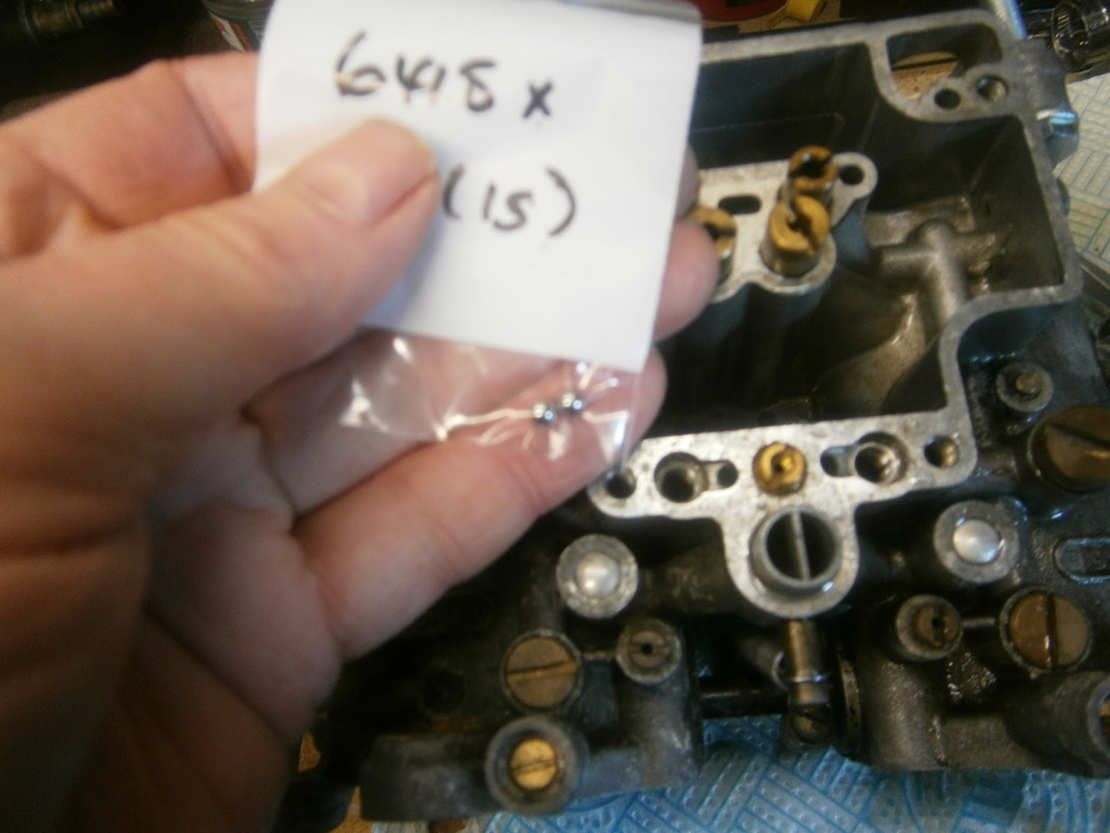 |
| New balls please! |
After assembly the car started relatively easily but running was very rough, apparently missing or spitting back occasionally, and rocking rather a lot. BUT.... on the credit side the excessive fuel in the rear carb has GONE (Hooray!!!) and I think therefore that the acceleration pump was the problem. I might have found this sooner were it not for Mr Hammill's advice. I know that this is well meant, and probably sensible if your car is relatively new (or at least well maintained!). In my case, it simply made me think the accelerator pumps were far too complex for me to fiddle with! Of course I still have to set them for the correct performance so this warning may yet come to pass, but at least I will be able to run the motor now to check.
So like a Knight of old I have now overcome the acceleration pumps in single mortal combat! Sadly, I cannot yet retire from the field covered in glory: there is still the problem of the excessively rough running, rocking/shaking and spitting of the motor- I appear to have wounded the beast but not yet totally vanquished it because running is far from acceptable! The story of the misfire and what was actually causing it is continued here!
No comments:
Post a Comment
Feel free to let me know what you think of this blog. I'm working on my own here so any feedback from those Lotus enthusiasts floating around "Blogger Bank" is welcome. Suggestions for process improvements especially welcome. If you like it please follow.