Having tried to grind in the valves manually, I did find that this was quite a lot of effort and very frustrating as the tool kept detaching from the valve heads (see my earlier post...). I therefore ordered a drill-mounted lapping attachment. The one I went for was German and made by BGS Werkzeug tools; its about half the price of the Gunson's EeZilap but seems just as robust- It didn't come with any instructions but wasn't too tricky to work out how to use ... and the Eezilap doesn't come with instructions either!
 |
| This is the German valve lapper. It comes with two different sized suckers to fit most valves. |
The lapper should be used at a max rpm of 1200, I think 1000 is about fine. I measured the rpm of my hand held drill using a handheld rpm meter (a really neat and cheap piece of kit usable on the pillar and hand drills as well as the lathe and even the occasional engine!). My drill was giving 350 and 1100 rpm on speeds 1 and 2 respectively. I think it will spin faster with a newly charged battery but as it was the high speed was pretty much perfect. The lapping arrangement is similar to the manual process. I fitted a small spring on the valve stem to help it lift between grinding bouts. Remember to
liberally lubricate the valve stem and guide, then apply some fine paste on the valve rim before lowering it into the guide and onto the seat.
 |
| Spring on valve stem to assist raising the head. Lubricate the stem with loads of engine oil. |
 |
| Valve inserted with spring to raise head |
The lapper then attaches with the sucker but make sure the drill is positioned in line with the valve stem lines... its easier to position the head with the valves you want to grind positioned furthest from you so that their stems are angled towards you and
not as shown in this pic as grinding away from yourself as shown here does get quite tiring.
When the drill is operated the valve is rotated in one direction unless you hold the larger disc section when a reciprocating motion is induced. I found it was easy to take a fairly light grip on the disc section so that the drill tended to oscillate and then slip through the fingers to a new position and then oscillate again, slip again etc. etc. You can monitor the slippage positions by looking at the movement of the screw heads in the top of the attachment. This means you can ensure that the valve is lapped in evenly. I allowed it to slip about 25 degrees each time and went round the valve seat twice.
 |
| Loose grip on tool, monitor slippage by looking at the screw head on the top of the disc section. |
 |
| Valve seat before lapping- heavy pitting. I think its an "evens" contest as to whether grinding or a seat recut is best. |
 |
| Same seat after lapping- great improvement- still not perfect but pretty good! |
|
The final step after lapping all valves was to clean the head thoroughly. I removed all the studs so that the rings of crud around their bases could be easily scraped off and chased the threads on all studs with an M8 die nut. I bought some small bottle brushes to make sure the valve guides were clean and then washed the whole head in paraffin followed by carb cleaner. Lastly I gave everything a good blast through with an air line, including the stud holes where a surprisingly large amount of muck was hiding.
Refit the valves (adding assembly lube to the stems) and springs and hey- job done! Now I need to finish the head that I've had serviced and then get on with the cam carriers!
I took the head to my local engineers- Southern Rebore Services who confirmed that all inlet valves and guides are fine and that only the exhaust valves/guides need to be replaced. They also examined and confirmed that the head does not require skimming for flatness and will therefore carry out only a "dressing skim" following guide replacement; in case the heating process employed during changing the guides should introduce a slight warping.
 |
| Head as returned from Southern Rebore... the original inlet valves (furthest from camera) weren't changed. These are higher than the new exhaust guides fitted closest to camera because... |
 |
| These guides are designed to accept a valve stem seal. |
Stem seals weren't an original Lotus feature but they seem a really good idea, especially for the exhaust guides which owing to the canted over position of the motor tend to run surrounded by oil. If fitting stem seals you must fit the spring seat first as this wont go over the seal!
 |
| Light skim to bottom of head as received from S rebore. |
 |
| Recut seats on exhaust valves. |
Bit mystified by the second head. The inlet valves ground as expected right ac ross the margin of the valve and the full width of the seat. This was the same as observed with the head above. However the new exhaust valves in the recut seats ground only across the centre section of the valve margin and seat... see pic.
 |
| Inlet valve (front|) and exhaust valve (rear) showing the difference in ground surfaces. |
This sort of behaviour is reminiscent of the triple angle seat cutting adopted in more modern motors, and not originally in the Lotus. I had asked for the seats to be cut as a single angle but this behaviour indicates that either they weren't... or perhaps the valves were already ground in the triple fashion around their edges. I will need to contact Southern Rebore and Kemp High Performnance to find out more about these points.
Well verdict from both was that yes this is a triple seat recut... shouldn't have been because the exhausts run hotter and so benefit from a good seat contact to the head to help dissipate the heat. However Kemp Racing confirm that overall this shouldn't make much of a practical difference if not a racing motor so advise its safe to go ahead and reassemble.
 |
| Inlet valves all fitted |
As noted earlier- the new guides are lower than the lotus originals as they are made compatible with a stem oil seal.
 |
| Stem seal no 8. |
These could be popped onto the valve guides by hand but in order to ensure that they went on straight and without damaging the rubber I used a seal installation kit- got thats econd hand on eBay at 5 quid and so a reasonable investment. I selected the installer that was about the same size as the valve stem and had a recess that accepted the seal
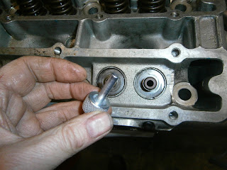 |
| Installer tool head |
 |
| ... slip on the stem seal.. |
 |
| and position using hand pressure. |
 |
| The carrier screws into the end of the drift |
 |
| and can be used to tap the seal home, whilst the projection keeps everything in line. Note the gap at the base of the seal here |
 |
| ... and now the seal is tapped fully home |
I applied red assembly lube to the tops of the valve seals and also the valve stems and inserted the valves from underneath. Here I was greatly assisted by using a Sealey head stand. This removes the need for two of the extra hands otherwise required to hold the head whilst using the valve spring compressor.
 |
| Head on Sealey head stand. A useful pieces of kit- but actually easily made so I wouldn't recommend buying it. |
The stand allowed me to use a more suitable valve spring compressor. An extra bonus was that the stem seals now gripped the valve stem so they didn't drop out as soon as you let go of them. This eliminated the need for the third extra hand reducing the number required in total to 2... and thus making the job feasible.
 |
| Draper valve spring compressor in use- I went for the largest version for ZETEC motors. Probably overkill as it was a little unwieldy- the next smallest would have been fine. |


