Search for tasks- type in keywords

Showing posts with label lotus excel. Show all posts

Tuesday, 7 March 2017

Getting towards the end? Bleed brakes, refit bonnet and strut

Well constant reader- Amazingly I am beginning to run out of tasks on this car and I think its time to be methodical about whats left so that I don't forget anything. There are a number of small jobs I've been leaving, but I'm now ticking them off and this is what I've done so far.

  • I tightened up the upper suspension arm-to-chassis bolts now that the car has been standing on its own "feet" for a while; 50 ftlb as specified. 

Upper suspn arm seen from behind front wheel. But and locknut.
  • I replaced the (new) rubber boot on the LHS track-rod end that had split as it was mounted. 
  • I needed to tighten up the exhaust cam-cover bolts as there was an oil leak on longer running and also the water pump to manifold hose- a short and troublesome length that is awkward to mount and awkward to tighten.
  • Clutch pedal action was heavy and had a tremendous drag- I adjusted the actuating push-rod by lengthening it (i.e. screwing it out of the clevis) and this solved the problem.

As far as recommissioning (yes I am really using that word), then the jobs left to do fall into three camps- there are a few that I need to do, a few that I will need to get done  (at time of MOT)and a few more that I am hoping will not be needed immediately to get the car on the road.

Jobs left for me (see on):
Bleed the Brakes: I have rebuilt but never commissioned the system. There was a problem bleeding the rear LHS caliper that I need to revisit. Hopefully just a blocked nipple.
Check brake fluid warning light:  the light so far has remained "on" in the dash.
Bleed PAS: No idea if this will still be fluid-tight.
Cooling system: Bleed heater and check otter switch.
Body: Refit the bonnet with a new gas strut- mine is meant for the classic range rover and part no MXC7833 which is a recognized substitute
... and that's basically it!!!

Jobs I will need to get done:
There are still a couple of jobs I will need to get done by the professionals: The exhaust needs changing (too mucky and awkward for me I will treat myself to getting that done by a specialist) I do have replacement stainless steel boxes but I'm missing the centre to rear box connecting pipes. The wheels need aligning and the body mounting points at the rear and all 4 jacking points need to be strengthened. I'm getting that done by Miles Wilkins- the Lotus fibreglass Guru (Fibreglass Services), but as his workshop is around 50 miles away, I need to get the car on the road before I can drive it over to him. I am hoping it will pass the MOT as is, then I can drive it over to Miles. Otherwise I may be looking at a trailer. Other jobs; like sorting out the exterior paint finish and fitting a new headlining are also professional jobs- but neither is necessary to get the car on the road.

Jobs I am hoping will not be needed yet:
Once I have sorted this, then I will have dealt with everything mechanical on the car except the transmission beyond the clutch. The gearbox and rear axle are Toyota items and I'm expecting them to last forever.
However,  I haven't changed much of the suspension- Its true that I have changed front upper ball joints and bushes but I left the lower arm and tie rod alone. (I do have lower BJs to fit but both these and the arm bushes there can be troublesome and I don't want to tackle them unless I have to). Similarly I haven't touched the rear suspension arm bushes or any of the shock-absorbers. These are easier to change, but expensive. I'm not going to change these items immediately unless  I know that  I need to- hence the need for an MOT examination.


So... progress to date:

Bleeding the Brakes:
I removed the rear wheel LHS and tried again to bleed through this caliper. Still nothing either using the pedal or my vacuum bleeding system.
I removed the nipple:

The bleed hole was completely blocked. I think this is grease left over from removal of the pistons- This was an effective method to shift them but clearly needs rather more careful cleaning than I had appreciated. I had expected the grease to be easily forced out by the pedal but this seems not to be the case. I cleaned the nipple and replaced it- sadly still no joy. I cleaned out the cavity with brake cleaner spray and then depressed the pedal. Luckily fluid now came through and I was able to pump a lot through to shift any cleaner left inside.

At this stage I bled all the brakes. I used a one-man vacuum bleeder. This is easy to use, but its virtually impossible to tell if you have actually bled anything properly because the vacuum draws air in around the nipple threads. You need to keep the nipple as done-up as possible and only use the lowest vacuum you need but even so I was still getting a froth. At this point I gave up and used my Ezibleed from Gunsons-
Using the Ezibleed pressurised from spare wheel.

This worked first time and showed clear un-bubbly fluid from the start so its likely that despite appearances the vac bleed had done a good job. The only problem is that it leaves the reservoir too full to re-insert the float cylinder on the cap so I had to remove some with a pipette.
Ezibleed leaves reservoir over-full...

... so I removed some fluid with a pipette.
The pedal still feels spongy- although I do now have brakes for the first time ever (!). I do have to pump them and this is typical of air remaining in the system somewhere. I have read that air can be trapped in the master cylinder and/or G valve so I will see about bleeding those.

Since the brake lines enter the M/C at the side, bleeding can never remove any air trapped above their entry position. This is really important if the cylinder has been removed and emptied... as has mine! For this reason the M/C should be completely filled (primed) on the bench before fitting... And I didn't do this. The holes are then plugged whilst the cylinder is refitted and finally the pipes are quickly attached so as not to loose the priming fluid. Sounds messy and I will need some caps for pipes and plugs for sockets. I will sort something out for this before I attempt the job or I can see brake fluid spread everywhere.

The G valve is positioned higher than the M/C- it is arranged in line upwards though, such that fluid passing through does follow an ascending route which should flush out any air- but maybe not always. The trick is to take it off and angle it so that the exit point is vertical and any trapped air can get flushed out and then loosen the top pipe union. This is simpler to do than removing the MC so I'll try it first. In the meantime, and presumably because someone had been tinkering with it in the past, the G valve was lacking a nut which I fitted.
G Valve fixed to the side of the car in front of clutch MC. Its angled upwards at about 45 degrees. Oddly, it seems to be held on by one stud (now with a new captive nut) and one or two pop-fittings that engage in plastic lined pockets in the car side?
I started by tackling the G switch- I connected the Ezibleed and then loosened the hose union at the top of the G valve to let any trapped air bleed out. If there was an airlock here then it wasn't vast and I didn't detect any air leakage. However, I checked the effect by re-bleeding the brakes- running 150 ml through each rear nipple and about 100 ml through the fronts to be sure I had exchanged the fluid and hopefully shifted any bubbles. Again I wasn't aware of any bubbles being flushed out, but after this- and to my delight, I got a firm pedal!

Brake fluid warning switch
The brake fluid reservoir warning switch continued to puzzle me. It comes on with the ignition; both handbrake and fluid warning switches illuminate, and they both remain on when the motor is running. Letting the handbrake off extinguishes that warning light but not the fluid warning. The simple explanation for this is that the handbrake is on and there's no fluid in the reservoir so I topped it up. Now both lights came on and off with the handbrake- which  is better but still not what I expected;  I had expected the fluid level switch to remain off when the motor is running regardless of handbrake action. I suspected that the brake switch was malfunctioning- but it was an easy clip-fit to take apart.

Disconnecting leads from the brake fluid sensor switch in the cap of the reservoir

Sensor section of switch: The underside of the lid (left) contains a plunger which rests on the float seen inside the cylinder on the right. When the float is high it pushes the plunger up breaking the connection between the two lugs on the upper side. When fluid level falls the float sinks and the plunger descends closing the contacts in the lid and earthing the brake fluid warning light which illuminates.

... and inside its a simple float and switch assembly. There were no obvious problems and testing the contacts revealed that depressing float closed them, raising the float opened them so it seems to work. I reassembled and refitted the switch. I studied the wiring diagram some more and I think I have the explanation:
Both H/B and fluid warning lights are fed from a common source (ignition activated post "D"). Each is earthed by their respective switches to turn on the lights. However the two circuits are separated by a diode such that the fluid warning light can earth through the H/B switch or its own switch, but the H/B light can earth only through its dedicated switch. This means the fluid warning light will come on whenever the handbrake is on, but it can also come on if fluid is lost when the handbrake is off. However, when it does this it will not turn on the H/B light. I tested this using the test plunger on the top of the M/C and it does indeed behave this way. This seems a primitive function compared with more modern cars, but nonetheless it does seem to be how it is designed to work! So this job done.

Bonnet and gas strut
The new struts were supplied as a pair- but even so were cheaper than getting just one from a Lotus supplier. Both ends have ball-and-socket joints and the new strut has sockets so the balls need to be reused. One of these was retained in the bonnet
Ball joint remaining on the car bonnet

Top end of gas struts- old (lower) and new (upper) both have sockets to accept the ball.


and the lower one had been removed with the strut when it was detached.
Lower end of gast strut- old strut with ball joint present

ball popped out in a vice

This simply popped out of the old strut and into the new, I greased it with a smear of copper grease. At this point I noticed that the mounting bracket was a little rusty so I've removed that and repainted it, as well as cleaning up the two mounting bolts.
repainted bonnet bracket.
The bonnet was very tricky to refit alone- but it is possible using a combination of wooden props and packers. The bonnet, strut mount, strut, washer tube and earthing strap were all fitted successfully.
Bonnet refitted, I may need to adjust the plunger pins but its closes and pops open ojn both sides so its not that far out.

Body/Trim extras...
I am guessing that I will never finish fiddling/renovating the trim and I did notice that the glove box has a hole where a blanking plug is missing- I've ordered a couple of 1.2 cm black plugs which will hopefully fit.
Inside the glove box: Missing plug on left...

... plug present on right.
The new plug wasn't quite the right size but I covered the  plug section with a ring of tubing and it was then perfect and pushed firmly into position. I find these little things unreasonably gratifying- pathetic really isn't it!
New plug inserted.
PAS
I summoned up the courage to bleed the PAS. I checked the reservoir was full, started the motor and turned the wheels from lock to lock a few times. Turning, amazingly, did get easier. I topped up the reservoir again. Turning the wheel with the motor off was much harder so there really is some pump assist action. I checked and no sign of leakage so job... I hope... done!

I am now nearing the end of my task list! Never thought I would get here but it really shows itself as the "moment of truth"- Hopefully everything I have done will hold together. I really need to road test the car but obviously with no MOT, its not road legal. There is a limit to what I can achieve on the drive and I guess the first time I get to see how it performs will be on the way to the MOT! In the meantime I still have reservations over the electrics (battery seems to run down) and the cooling system- being sure that its bled and doesn't leak but the otter switch (fan switch) in particular. Although I have repaired the fan and refitted the switch (and it doesn't leak), the fan has never come on and this is obviously concerning. It may simply be that my idling on the drive has never reached 90 deg in the top hose and (Duuuh!!) I didn't check the switch while it was out. I have however ordered a new hose adaptor which will take a threaded fan switch so I can always insert this later.

In the meantime- at this milestone I think its appropriate to look at how far I've come and so here are a few before and after pics of the engine bay....hopefully you can see which is which! Photography has improved if nothing else!


Saturday, 25 June 2016

Induction system; Air box and trunking

When I got the car the air box was in the boot attached to a degraded length of trunking. The time is now ripe for looking at this more closely in preparation for eventual re-fitting to the car. The box was in two pieces and no filter present. The air trunking I had assumed to be a simple tube- however it turned out to be multilayered featuring a foil layer, a spring, some foam and possibly even an asbestos layer! This didn't seem right so I suspect someone has substituted a length of gas fire flue lining??? Anyway I disposed of this (carefully) measuring the size of the box and also the Venturi plug inserted at the other end. Both were fastened with a degree of invention- duct tape and silicone, so once more that suggests that this isn't an original air duct. Both air box and Venturi need a hose that is 3.25"  internal diameter so I will investigate and order a replacement.

In the meantime I looked at the filter box; latches are pretty rusty so I detached these to soak in de-ruster DeoxC. Each of the 4 latches is held on by two M3 cross head screws going into M3 5.5 mm captive nuts (handy size or what??)
Airbox lid- 4 latches all rusty

Typical attachment- 2 crossheads with washers beneath going into 5.5 mm captives.

Nuts seen here.
I removed all fittings and left to de-rust in DeoxC. There was also a long spring- I'm not sure what this is for but it was attached as shown in the next few pics and I removed it also to de-rust.
spring

spring attachment- a second hole in the box and the spring is inserted directly into the box frame.
The box was missing both attachments; a split pin/washer for the throttle cable support, a clip for throttle spring support* and also the crankcase ventilation hose. I will need to find if any are lying about loose and can be refitted later. I have since identified the long spring as the throttle return spring. This has been clipped directly into the air box, presumably because the  split pin mount has been lost. The seal for the air box is also missing although this may be supplied with a new filter (have checked, it wasn't with mine!).

* I can find no trace of this support- according to the parts diagram its part number X026S0074Z and it should be pop-rivetted to either the box or the induction hose. I cant find the pop rivet or even a hole so I will do without this for the time being.

I refitted the treated latches using the same screws and improvised a spring attachment using a split pin.

latches de-rusted and refitted

split pin attachment for throttle return spring.
My new paper air filter already had a thinnish rubber edge to it but not enough to stop it rattling around in the airbox. According to the parts list the two parts of the airbox are sealed onto the filter element with a rubber seal C907E0588F which I think must replace this skinny filter edge.  However it seemed to me to a better idea to use some rubber sealing channel as I had some lying around and fix this to the box not the filter so it didn't need to be removed everytime you change the filter. This is narrow, split rubber channel edging (1cm section) from Woolies at £3.50 a meter- and 3 meters is enough for two boxes. This clips onto the edge of the inner section of the airbox and fits neatly inside the recessed half to give a nice looking join and holds the filter securely.

Split seal from Woolies- appx 1cm cross-section


Clips onto box edge

All the way round...

Cut to length and seal with rubber cement from a puncture repair kit

Box then clips together neatly and holds the filter tightly


The ducting is part no  B907E0836W in these early cars and should be fastened to the air box with a large wire clip (present), the fan cowling with a plastic tie (absent) and with an O ring (also absent)which should fasten the duct to the clip like feature that mystified me earlier on the radiator bracing strut.  I ordered some 89 mm nitrile induction hose which came with two large clips that I hope will be enough to snug it down onto the airbox and venturi at each end.

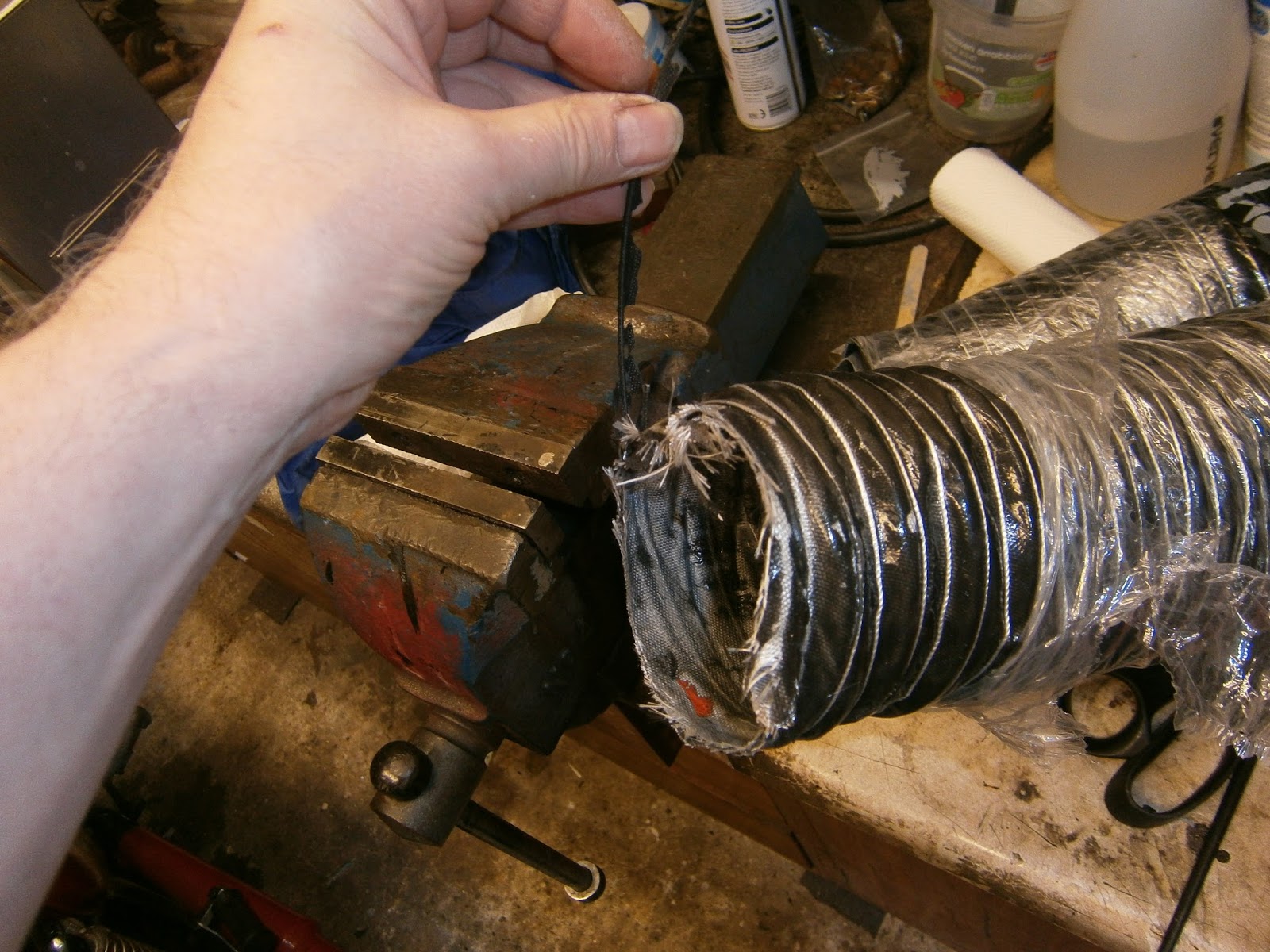
 The hose I bught was about half the [price of a Lotus recommended part from the usual suppl;iers, but the consequence of that is that the ends arent finished. The hose is reinforced by a helical wire and this is left loose where it was cut. To stop it unravelling further Locate the protruding end of wire and bend the last 1.5 cms over at 90 degrees.

Bend the wire back down the hose and poke the 90 degree section through the hose wall beyond the next turn of wire
wire poked through hose below next turn of wire.

Check wire is routed round the edge of the hose, not acroos the void.

And fold the protruding wire back flat over the internal turn of wore in the hose wall.

Trim off the frayed ends

And use Ducktape and or exhaust tape as whipping to bind the frayed and and provide a smooth surface for eventually mounting the clip.

End prepared
 The venturi that came with my car had a few bite-like chunks taken out of it. I doubt this will make much difference especially in a lc motor but hey, if the venturi wasn't doing anything I doubt it would have been included so I filled the missing sections with isopon
Isopon infill- smoothed down and...

Sprayed black ready for installation.

The airbox, hose and venturi are now ready for installation but obviously this wont happen until the motors are swapped so for the time being I'm storing the parts. 

Tuesday, 14 June 2016

Renovation upper suspension arm (wishbone), pivot bushes and upper ball joint

I was hoping not to have to tackle any of the suspension in order to get the car through the MOT. I did know that the job would need to be done eventually (soon), but I had hoped to have a bit of a financial rest first! However, on removing the front right wheel to attend to the brakes, I found one of the ball joint boots was split and that opened up the whole can of worms!
LH front upper ball joint- boot split

That said, it is true that now, whilst I have the hubs stripped off to deal with calipers and discs, is a very good time for the necessary access to do these jobs! Obviously I will need to do something to this joint as a split boot is a guaranteed MOT failure. It's possible that just rebooting the upper ball joints would do, but if I would need to detach the vertical link/stub axle anyway, so it's just as easy to change the ball joint and I will do the top arm bushes as well. The upper arm is not under spring tension. The spring is contained between the chassis and lower arm, it's extension being controlled by the shockabsorber. This means that it can be safely dismantled without worrying about spring compressors. However this is not so for the Lower arm and all reports suggest that lower arm ball joint, pivot bush and anti-roll bar bushes are likely to be very difficult: both because of needing to control the spring and because they are tight and hard to fit as well. Despite the golden opportunity that this access provides, I think I will leave the lower arm until I find out if they need doing immediately at the MOT. Strange after all this time to be actually thinking of the MOT!!!

I started the upper arm strip by loosening the ball joint bolts
 Followed by the ball joint itself, the taper broke easily with a BJ tool, the boot looks worse than I was expecting!
 I was puzzled by the inner pivot, there are two nuts (i.e. a nut plus a locknut) on the forward side-
My initial plan had been to remove the nuts at this end and then tap the pivot out towards  the rear. However it quickly became apparent that there is insufficient clearance to the front or back for the pivot bolt to be removed! I Guess it must have gone in before the body was attached- so good one ACB! However the process is simple- you just need to remove the nuts from both ends (hence the need for the locknut) and then separate the sides of the upper arm at the ball joint and remove each separately. There are 2 washers flanking each arm.
Lock up the locknut by unscrewing the rear nut tightly up against the locknut. Hold the nut tight and...
Remove the rear nut, note the washer between nut and arm.


You can then remove the lock nut  from the forward side

... and then remove the second nut, note washer!

Rear spar of top arm. Note second washer between arm and chassis mount
One wishbone removed. Its not necessary to tap out the pivot bolt as shown here- that was left over from my abortive first attempts.


Ball joint removed- pretty terrible state!
 I also intended to replace the inner pivot bushes in these arms- I'm using rubber metalastic basically because they are so much cheaper than polyurethane. In fact they didn't look in bad condition anyway,  but while the arms are off.... I had intended to use this Draper press and pull kit, but there were two problems- firstly it didn't have any press adapters small enough and secondly its really intended for working on an arm whilst it is still mounted on the car. This is because its really hard to both support the arm off the car and apply force to the extractor bolt. However in this case where clearance was so limited its pretty much impossible to use the screw method in the car. Anyway I used the  threaded puller from the set combined with a deep (23mm) and a shallow (19mm) socket to press out the bush on the bench. This was hard work but succeeded with the first bush.

Sadly though, I just couldn't apply enough force to the second arm and resorted to a bench press to shift it. Inspection of the removed bush showed that it had been "shaved" as it was originally pressed in, the outer casing had been scraped off.

Bushes as removed- sides pretty much shaved. LH bush is the one that was difficult to remove. A shiny spot on the top shows where it was binding.
I suspect therefore that it is much easier to press out if its pressed back out the way it was originally pressed in. Pressing it further  in the direction it was inserted would mean shaving the last section of bush metal coat and this would take a LOT of force. I think therefore that when I used the Draper screw press method, I was probably pushing it the wrong way! - Not that there is any way of telling which way (if any) is actually the right way! Anyway it popped out really easily in the press. It might be worth trying to decide in which direction the bushes were fitted when removing- although there may be no obvious sign.
I degreased the arms and soaked them in DeoxC before rinsing, Jenoliting and finally spraying in Aldi black metal protection paint.


I stripped the other side and prepared it in the same way. I fitted the new bushes using the bench press. For this I supported the arm using. Nielson press plate. Very pleased with that as it was a lot cheaper than the Sealey version and worked fine. For the amount of use I will give it, it should last me fine.

Lubricated bush with corrosion protect grease and placed it in position Upper arm in this pic has already had the new bush inserted


Arm supported on Neilson plate

Started pressing with arbor only- here bush is halfway

Complete using a socket to press bush lip into arm

Discbrake dustshield  re-fitted, again this was done using loctite threadseal as I do not want these working loose.


I assembled the upper links with their new ball joints and bolts onto the chassis, I tightened the ball joint up whilst everything else was loose so it could be drawn into alignment via the vertical link. Final tightening will be done once the car is standing on its wheel so all bolts left loose at this stage.
Ball joint-upper arm bolts tightened to 15 ft lb