Well dear Reader, I started this blog to document the restoration of a fresh hedge-find, or at least a basket case of an Excel. I think this car didn't really want to be rescued, perhaps it was happy quietly returning its constituents to their natural state, and its fought me every step of the way. There have not been many occasions when something I checked turned out not to need attention.
However today is a milestone, a red letter day: The car has its first MOT!!! I've now been able tax it for the first time since 1990, bringing to an end ending 27 years of off road existence!!! Obviously there will be more work to do, not to mention ongoing maintenance (and the repair to the bumper!), but much of this will be done by professionals as I don't think I am neat enough to fix a headlining, fibreglass a repair or carry out a respray. So this is, as they say, the end of the beginning!!! I will post more about anything I need to fix but (hopefully) this will not be so regular. In the meantime, thank you for coming with me on this part of my journey into Lotus land.
Wednesday, 24 May 2017

Friday, 19 May 2017
Still waiting part 2: From bad to Worse!!
Welcome back faithful reader! I know I have only 1 follower so he or she has been busy viewing my blog nearly 45,000 times! So, whoever you are thank you!!!
If you have been following me for the last 2-3 years you will know what I have been through. The project eventually limped towards road-worthiness but who would have predicted the trials and tribulations so close to becoming road legal!!
Well you will know the problems with the exhaust. I have been trying everywhere to get a LC motor (non SE) system. Finally I think I've succeeded and PNM Engineering came through for me with possibly the last genuine Lotus pre-SE system in the country!! Sadly it wasn't complete and needed a new Y piece but this was made by the same company as the original from the original jig. It also lacks one back box... but hopefully mine will fit.
However waiting for the system to be assembled and dispatched has been purgatory. Finally its on its way and arrival expected on Monday... By then the garage will have had the car for 4 weeks! Apparently customers have been asking about it... I'm hoping in a good way!!
Dropped the exhaust off at the garage today. My car visible with boot open. Garage were charging the battery (thank you!) which means the battery has run down again despite my having found no earth leakage! I'm beginning to think this cheap internet Exide is a either a knockoff or just faulty and just can't hold charge. Uhfdistribution, trading via Ebay, have offered to refund me... but only if I return the battery (at my cost) and it then fails their (unspecified) test. If it doesn't then I think mailing it back to me would still leave me with a potentially duff battery and is also going to be at my cost ... none of that is cheap. I will test again for current leakage and maybe bite the bullet and get a genuine Yuasa locally. Lesson learned I think!
Update:
The new exhaust is on... apparently it fitted like a dream. Once again, despite my request to try the downpipe alone the message didn't reach the fitter and the whole thing was changed. This means I still don't know if the other system would have fitted if the garage had done as I asked and left the original down pipe which was the only part if the old system I thought that was salvageable. If so then that would have saved me £500 spent buying the new system. Also, given that we are where we are, had the new downpipe alone solved the problem it would have left me with a quality part system to sell on and recoup something of my costs. As it is the old system has been returned to me but it will be difficult to sell on as I don't really know what is needed to make it fit! However this minor gripe is a small problem compared with my later woes:
The new exhaust is on and sounds lovely. So nice in fact that it tempted the fitter to take for a test drive... not usual I think after an exhaust swap. Sadly the fitter then pranged it and I now have significant front end damage!!!


This will mean at least a new front bumper and I'm hoping that the nose and bonnet aren't damaged. To add insult to injury the garage had forgotten that the car was originally in for an MOT not simply an exhaust swap so its still not been assessed. It remains road-illegal!!!
This is getting very disheartening.
If you have been following me for the last 2-3 years you will know what I have been through. The project eventually limped towards road-worthiness but who would have predicted the trials and tribulations so close to becoming road legal!!
Well you will know the problems with the exhaust. I have been trying everywhere to get a LC motor (non SE) system. Finally I think I've succeeded and PNM Engineering came through for me with possibly the last genuine Lotus pre-SE system in the country!! Sadly it wasn't complete and needed a new Y piece but this was made by the same company as the original from the original jig. It also lacks one back box... but hopefully mine will fit.
However waiting for the system to be assembled and dispatched has been purgatory. Finally its on its way and arrival expected on Monday... By then the garage will have had the car for 4 weeks! Apparently customers have been asking about it... I'm hoping in a good way!!
Dropped the exhaust off at the garage today. My car visible with boot open. Garage were charging the battery (thank you!) which means the battery has run down again despite my having found no earth leakage! I'm beginning to think this cheap internet Exide is a either a knockoff or just faulty and just can't hold charge. Uhfdistribution, trading via Ebay, have offered to refund me... but only if I return the battery (at my cost) and it then fails their (unspecified) test. If it doesn't then I think mailing it back to me would still leave me with a potentially duff battery and is also going to be at my cost ... none of that is cheap. I will test again for current leakage and maybe bite the bullet and get a genuine Yuasa locally. Lesson learned I think!
Update:
The new exhaust is on... apparently it fitted like a dream. Once again, despite my request to try the downpipe alone the message didn't reach the fitter and the whole thing was changed. This means I still don't know if the other system would have fitted if the garage had done as I asked and left the original down pipe which was the only part if the old system I thought that was salvageable. If so then that would have saved me £500 spent buying the new system. Also, given that we are where we are, had the new downpipe alone solved the problem it would have left me with a quality part system to sell on and recoup something of my costs. As it is the old system has been returned to me but it will be difficult to sell on as I don't really know what is needed to make it fit! However this minor gripe is a small problem compared with my later woes:
The new exhaust is on and sounds lovely. So nice in fact that it tempted the fitter to take for a test drive... not usual I think after an exhaust swap. Sadly the fitter then pranged it and I now have significant front end damage!!!


This will mean at least a new front bumper and I'm hoping that the nose and bonnet aren't damaged. To add insult to injury the garage had forgotten that the car was originally in for an MOT not simply an exhaust swap so its still not been assessed. It remains road-illegal!!!
This is getting very disheartening.
Thursday, 27 April 2017
Still waiting...
Well things have gone really tits up in the last few days (.Y.)...
The car is still at the garage and they have had all sorts of problems fitting the new exhaust system. So much so in fact that they questioned as to whether it was the right exhaust for the car. I have however checked with lotusbits from whom I bought the missing sections of my exhaust system. These consisted of the Y piece and two small tubes which connect the Y piece to the tail boxes. Lotusbits assured me that everything is correct. Although there are two types of exhaust for this car they are distinguished by the pipe mating flanges. Provided the flanges match my boxes, and they do, then the pipes are correct. The problem may have arisen from the way in which the garage tried to fit the exhaust. Apparently they fitted it initially by raising the car on a two post ramp. Raised in this way the wheels hang free. Apparently the exhaust fitted perfectly like this but when the car was placed back onto its own wheels then it was found that the exhaust contacted the prop shaft, chassis and rear bumper. There is limited room for manoeuvre with this type of exhaust because of the flanged conical joints. However lotusbits tell me that the secret is to twist the pipes into the correct position whilst the car is load bearing so the garage will have another go at this tomorrow using a 4 post lift. However, they have by now had the car for a full week. I would imagine that they are getting very impatient. I do not want to annoy this place because in the end they control my MOTs and so access to the road. If anyone reading this has any hints as to how such an exhaust can be successfully fitted please feel free to PM me.
The situation is made even worse since the usual supplier of new low compression engine exhausts has apparently gone into receivership. Although wide bore exhausts are still available they are clearly not right for my car. Not to mention the fact that they cost nearly twice as much. Even so if I were forced to use such an exhaust the lead time would be 6 weeks. All in all things are not looking so bright. I sincerely hope the garage manages to fit the exhaust correctly tomorrow.
Sadly they didnt get time on the ramps- and then the bank-holiday intervened so here I am nearly 2 weeks now and still no answer.
I realise that the ramp access problem is down to the garage, but it seems exhausts on the Excel are pretty notorious. Most problems occur on the later SE models when Lotus farmed out exhaust manufacture to two companies (Peco and Grundy) each of whom used their own jigs to manufacture similar-looking but mutually incompatible systems. Apparently this is where the Lotusbits specification for matching flanges comes from. However during the low compression Excel era I think Lotus made only one type of exhaust (distinguished as the SE systems both have different manifold down pipes) which is supposedly easier to fit. Given that there are therefore at least 3 different and incompatible original exhaust systems out there (not to mention the legion of later pattern parts with/without flanges made using these as templates) it does seem that the process of assembling a system from component parts was actually pretty much doomed to failure! I was told that everything is compatible- and I did check, but at this remove was anyone really certain what parts had come from where?
I am promised that the garage will have another crack at the system tomorrow and should at least know if I have to pursue a complete replacement... although I now have doubts whether even a new exhaust is likely to fit any more easily!
The car is still at the garage and they have had all sorts of problems fitting the new exhaust system. So much so in fact that they questioned as to whether it was the right exhaust for the car. I have however checked with lotusbits from whom I bought the missing sections of my exhaust system. These consisted of the Y piece and two small tubes which connect the Y piece to the tail boxes. Lotusbits assured me that everything is correct. Although there are two types of exhaust for this car they are distinguished by the pipe mating flanges. Provided the flanges match my boxes, and they do, then the pipes are correct. The problem may have arisen from the way in which the garage tried to fit the exhaust. Apparently they fitted it initially by raising the car on a two post ramp. Raised in this way the wheels hang free. Apparently the exhaust fitted perfectly like this but when the car was placed back onto its own wheels then it was found that the exhaust contacted the prop shaft, chassis and rear bumper. There is limited room for manoeuvre with this type of exhaust because of the flanged conical joints. However lotusbits tell me that the secret is to twist the pipes into the correct position whilst the car is load bearing so the garage will have another go at this tomorrow using a 4 post lift. However, they have by now had the car for a full week. I would imagine that they are getting very impatient. I do not want to annoy this place because in the end they control my MOTs and so access to the road. If anyone reading this has any hints as to how such an exhaust can be successfully fitted please feel free to PM me.
The situation is made even worse since the usual supplier of new low compression engine exhausts has apparently gone into receivership. Although wide bore exhausts are still available they are clearly not right for my car. Not to mention the fact that they cost nearly twice as much. Even so if I were forced to use such an exhaust the lead time would be 6 weeks. All in all things are not looking so bright. I sincerely hope the garage manages to fit the exhaust correctly tomorrow.
Sadly they didnt get time on the ramps- and then the bank-holiday intervened so here I am nearly 2 weeks now and still no answer.
I realise that the ramp access problem is down to the garage, but it seems exhausts on the Excel are pretty notorious. Most problems occur on the later SE models when Lotus farmed out exhaust manufacture to two companies (Peco and Grundy) each of whom used their own jigs to manufacture similar-looking but mutually incompatible systems. Apparently this is where the Lotusbits specification for matching flanges comes from. However during the low compression Excel era I think Lotus made only one type of exhaust (distinguished as the SE systems both have different manifold down pipes) which is supposedly easier to fit. Given that there are therefore at least 3 different and incompatible original exhaust systems out there (not to mention the legion of later pattern parts with/without flanges made using these as templates) it does seem that the process of assembling a system from component parts was actually pretty much doomed to failure! I was told that everything is compatible- and I did check, but at this remove was anyone really certain what parts had come from where?
I am promised that the garage will have another crack at the system tomorrow and should at least know if I have to pursue a complete replacement... although I now have doubts whether even a new exhaust is likely to fit any more easily!
Saturday, 22 April 2017
Last minute preparation
Well we are nearly there!! I have a few last minute things to bolt down, fit on or adjust and then it's off for the MOT test- for the Americans reading this blog, this is the annual road-worthiness assessment that every car over 3 years old must undergo in order to be driven legally in the UK. Its a very useful check on the general deterioration of a vehicle in the UK climate and also on the safety of any repairs. Its both useful and feared at the same time. If I could find a virgin I would sacrifice her (or her virginity?) to the almighty Gods of the MOT... but as I can't (they are rarer than hen's teeth round here) I am simply having to trust to luck.
Obviously its daft to fail on simple things so a last minute pre-test check is advisable, and of all the jobs I have to do most are very simple I need to:
1. Adjust the clutch pedal for smooth disengagement.
Checked- I think its OK and won't change it until I have tried it in use on the road.
2. Secure the battery using the battery clamps, but don't refit the battery cover as the tester will need to check battery security, and also I don't want to damage the flimsy cover because I also have to...
3. Assemble the new exhaust system and fitting kit and put them in the boot ready for the garage to fit.
I have assembled a collection of stainless steel nyloc nuts, washers, and bolts of the correct length (6 x 40mm M8 and 12 x 30mm M8) plus rubber hangers of the correct types (4 each), so that the exhaust can be fitted securely. I have also supplied a manifold-to-downpipe gasket although this might not be needed.
4 Re-route throttle cable and fit a new (or extra) spring to the throttle return arm to stop it sticking slightly on.
I shortened the spring and refitted it- the throttle now no longer sticks and the pedal has a good positive pressure when pressed.
6. Refit air filter and induction system.
I refitted the box but not the filter as the carbs were setup without it and I want to give them the best possible opportunity to breathe and thus meet the emissions standard specified in the test.
7. Fit the locking wheel nuts as there are currently only 3 nuts per wheel!
I bought a new Krooklock set years ago but have never needed to fit them- had entirely forgotten that I have had only 3 nuts per wheel for the last 2 years!
I also discovered that one wire on the driver's door mirror had broken. There are 4 wires to each door mirror and each terminates in a male mini spade connector which just pushes into the back of the mirror. This arrangement takes up very little room fits under the cover smoothly. I didn't have anything suitable to replace these connectors so I reused the old terminal, carefully unpicking the crimp and soldering on a short extension wire, covering the join with heat shrink.
Assuming the car actually makes the trip to the MOT station OK (in my case about a mile and a half), then I am also asking the garage to do some work for me.
Firstly, I want them to fit the second hand stainless steel exhaust system I have assembled from a variety of sources. I could do this myself, but without a decent ramp it will be difficult and unpleasant. Plus I am only asking the garage to change those parts of the system that need to be changed. Although I am supplying a complete system, I think some parts such as the down pipe from the exhaust manifold, may be in good enough condition to leave. Leaving this will make the job both quicker for them and hopefully cheaper for me. I need the Garage with its eye to the MOT to make that judgement call.
Secondly, I have changed the steering rack and track rod ends (as avid readers of my blog may recall). This means that the tracking now needs to be adjusted -especially as I have new tyres front and rear and don't want excessive wear on them so early in their life.
These things then are what I can control, but even so I do not expect the car to pass the test. I can't think of anything specific that it will certainly fail on, but on the other hand I don't know for certain that even those jobs I have done will pass. I am also worried about those parts of the car that I haven't touched - and really this means all of the suspension with the exception of the forward upper arm bushes and upper ball joints. I.E. ARB bushes, rear supension bushes, lower arm bushes and ball joint, all springs and shock absorbers. The car has only done 45,000 odd miles so I am hoping that some of these at least will still be roadworthy despite their age, and the shocks in particular are so expensive to change (coil-over replacements required) that I don't want to do such a job unnecessarily. For comparison I can change nearly all the shock absorbers on the MGB for the price of one Lotus shock! However, although I expect a fail, the MOT should result in a shortlist of jobs and I have a two week window (whilst my MGB is having its body work repairs) in which I can get on with trying to finalize the Lotus for its return to the road.
Note added after car sent for test...
Well the Lotus is clearly going to fail. I took it down this morning... It was pushed onto my drive two years ago by a hefty, heavily tattooed, ex naval Scotsman as a very sick car. Now some two years later and after many trials and tribulations (see blog!) I have been able to drive it off again under its own power: The first time I've driven it, and I think the first time its been driven in 10 years... and YES(!) we made it to the testing station!
On the credit side the motor was smooth and even and pulled really well. On the mildly irritating side I was wrong about the clutch... it does still need adjusting; and on the highly irritating side, a couple of the things I had already "fixed" broke again on the way down. I think I have said before that this car just doesn't seem to want to be rescued!
These are all things I have previously sorted and checked- wiper self cancellation was one of the first jobs I did on the car and its been fine from June 2014 right up to yesterday. I think its just possible that the heavy steering is caused by really awful wheel alignment which will be checked at the garage. I think that will improve matters but I doubt its going to fix the problem. Although I did get the rack reconditioned I did nothing to the pump except refit it so at the moment I'm guessing I really need a recon pump too. Still I will see what else the garage say and what light if any they can shed on the problem! Could just be a bleeding or belt problem Although it has to fail (headlamp alone would do it), the extent (and cost) of the jobs-to-do list remains in the lap of the Gods...
To Be Continued!
Well, I finally heard back from the garage... As expected the result was a fail. Surprisingly and gratifyingly practically everything I had done passed... I was notified of 7 fail items... But they made surprising reading.
1. N/s headlamp main beam inoperative
2. Headlight aim too high
3. N/s front tyre incorrectly fitted
4. O/s front tyre incorrectly fitted
5. Speedometer not capable of illumination
6. Track rod end locking nut loose
7. Emissions not tested due to poor state of exhaust.
Surprisingly the wipers seem to have parked themselves and the tester had sufficiently well-developed biceps that any deficiencies in the PAS went unnoticed! The damaged jacking points were not a failure item. All in all very good news.
Surprisingly though because...
Headlight failure is new, I had noted it as I drove down. The dip beam is still working so a new bulb should sort that out. I've never checked beam alignment... They have a gauge for that and I'd expected it to need doing.
Both my tyres are new and fitted on my drive by Etyres. This was a very good service. I think I must have swapped l and r wheels at some point and this probably accounts for in incorrect rotational direction. I think that's a more likely explanation than the fitter fitted them wrongly. Its not something I'd ever really considered as swapping tyre positions was formerly a normal part of service to equalize wear "in the old days" and I had never considered that wheels weren't interchangeable! If they aren't, where does this leave the role of the spare wheel? I need to get my head around this because the garage think that the tyres need to be removed and refitted which is a bit more expensive... I think just swapping the front wheels might sort them out. Well I have now checked my tyres... they are Nexen CP6450... Cheapish and mixed reviews... main problem seems to be road noise... (that would be novel for me as you need to be driving the car for that to be a problem!!). Anyway the point is that these are directional but they are not assymmetric so the arrow markings have to face the direction of rotation but inside and outside edges are not different. Consequently just swapping the wheels left for right should solve the problem without needing to remove and refit! This seems to have arisen from my error and I will know better in future.
I am bit concerned about the speedo light - might it not simply be a low setting on the panel light control? ... I didn't check that but I think the light worked when I last had the speedo out and its possible that the garage don't realize that such an early car even has a panel light control!
I'm not worried about the track rod nuts. I hadn't bothered to crank these up really tight because the car only had to make it to the garage and wheel alignment needs adjusting anyway. This was booked with the MOT and should put that right.
Well I'm probably being over cautious. I had initially decided to do these repairs myself, but that means removing the car from their premises and if the car has been moved then its always possible that they could find something "new". I know that in theory if you return the car in short order (7 days I think) they need only retest the fail items... but who knows? I don"t want to snatch failure from the jaws of success and have them find additional faults... I decided on balance to leave it with them and have them repair the fail items and trust that it then passes the emissions test. However having spent so much time prepping and repairing stuff myself, I am a little worried at having the garage do the repairs. After all its not a common car and they can't be familiar with it. For instance, if its not a panel light control issue, then getting the dashpod out to fit a new speedo bulb (BA9s) isn't straightforward, and I really don't want my carefully repainted instrument trim panel snapped. Similarly I'm a little worried in case they don't know how to remove the headlights without damaging the bezels or mounting pins... Neither of these were obvious to me at first and I had the manual and the forum to ask! I clearly have trust issues.
Well, they have now kept the car for a couple of days whilst they swap the exhaust, align wheels and attend to the fail items before repeating the MOT.
Obviously its daft to fail on simple things so a last minute pre-test check is advisable, and of all the jobs I have to do most are very simple I need to:
1. Adjust the clutch pedal for smooth disengagement.
Checked- I think its OK and won't change it until I have tried it in use on the road.
2. Secure the battery using the battery clamps, but don't refit the battery cover as the tester will need to check battery security, and also I don't want to damage the flimsy cover because I also have to...
 |
| Battery clamped in terminals reattached- wooden spacer required in front. |
I have assembled a collection of stainless steel nyloc nuts, washers, and bolts of the correct length (6 x 40mm M8 and 12 x 30mm M8) plus rubber hangers of the correct types (4 each), so that the exhaust can be fitted securely. I have also supplied a manifold-to-downpipe gasket although this might not be needed.
4 Re-route throttle cable and fit a new (or extra) spring to the throttle return arm to stop it sticking slightly on.
 |
6. Refit air filter and induction system.
I refitted the box but not the filter as the carbs were setup without it and I want to give them the best possible opportunity to breathe and thus meet the emissions standard specified in the test.
7. Fit the locking wheel nuts as there are currently only 3 nuts per wheel!
I bought a new Krooklock set years ago but have never needed to fit them- had entirely forgotten that I have had only 3 nuts per wheel for the last 2 years!
I also discovered that one wire on the driver's door mirror had broken. There are 4 wires to each door mirror and each terminates in a male mini spade connector which just pushes into the back of the mirror. This arrangement takes up very little room fits under the cover smoothly. I didn't have anything suitable to replace these connectors so I reused the old terminal, carefully unpicking the crimp and soldering on a short extension wire, covering the join with heat shrink.
 |
| Removing the 4 Phillips screws releases the mirror and motor unit |
 |
| Separating the mirror unit- Only 3 wires are attached to the mirror. Blue wire has broken, the old contact is seen still stuck in the motor unit below the brown wire. |
 |
| Refitting the old spade connector to a short fly lead |
 |
| Joining extension to mirror wire; heat shrink over join |
 |
| Mirror reconnected and cover replaced. |
Firstly, I want them to fit the second hand stainless steel exhaust system I have assembled from a variety of sources. I could do this myself, but without a decent ramp it will be difficult and unpleasant. Plus I am only asking the garage to change those parts of the system that need to be changed. Although I am supplying a complete system, I think some parts such as the down pipe from the exhaust manifold, may be in good enough condition to leave. Leaving this will make the job both quicker for them and hopefully cheaper for me. I need the Garage with its eye to the MOT to make that judgement call.
Secondly, I have changed the steering rack and track rod ends (as avid readers of my blog may recall). This means that the tracking now needs to be adjusted -especially as I have new tyres front and rear and don't want excessive wear on them so early in their life.
These things then are what I can control, but even so I do not expect the car to pass the test. I can't think of anything specific that it will certainly fail on, but on the other hand I don't know for certain that even those jobs I have done will pass. I am also worried about those parts of the car that I haven't touched - and really this means all of the suspension with the exception of the forward upper arm bushes and upper ball joints. I.E. ARB bushes, rear supension bushes, lower arm bushes and ball joint, all springs and shock absorbers. The car has only done 45,000 odd miles so I am hoping that some of these at least will still be roadworthy despite their age, and the shocks in particular are so expensive to change (coil-over replacements required) that I don't want to do such a job unnecessarily. For comparison I can change nearly all the shock absorbers on the MGB for the price of one Lotus shock! However, although I expect a fail, the MOT should result in a shortlist of jobs and I have a two week window (whilst my MGB is having its body work repairs) in which I can get on with trying to finalize the Lotus for its return to the road.
Note added after car sent for test...
Well the Lotus is clearly going to fail. I took it down this morning... It was pushed onto my drive two years ago by a hefty, heavily tattooed, ex naval Scotsman as a very sick car. Now some two years later and after many trials and tribulations (see blog!) I have been able to drive it off again under its own power: The first time I've driven it, and I think the first time its been driven in 10 years... and YES(!) we made it to the testing station!
On the credit side the motor was smooth and even and pulled really well. On the mildly irritating side I was wrong about the clutch... it does still need adjusting; and on the highly irritating side, a couple of the things I had already "fixed" broke again on the way down. I think I have said before that this car just doesn't seem to want to be rescued!
- The wipers no longer self-park- they did so happily yesterday but today its just too much trouble for them!
- The power steering has become lazy. Its weak-to-non-existent and doesn't feel particularly motivated to help me to turn the wheel.
- One headlamp main beam decided not to come on!
These are all things I have previously sorted and checked- wiper self cancellation was one of the first jobs I did on the car and its been fine from June 2014 right up to yesterday. I think its just possible that the heavy steering is caused by really awful wheel alignment which will be checked at the garage. I think that will improve matters but I doubt its going to fix the problem. Although I did get the rack reconditioned I did nothing to the pump except refit it so at the moment I'm guessing I really need a recon pump too. Still I will see what else the garage say and what light if any they can shed on the problem! Could just be a bleeding or belt problem Although it has to fail (headlamp alone would do it), the extent (and cost) of the jobs-to-do list remains in the lap of the Gods...
To Be Continued!
Well, I finally heard back from the garage... As expected the result was a fail. Surprisingly and gratifyingly practically everything I had done passed... I was notified of 7 fail items... But they made surprising reading.
1. N/s headlamp main beam inoperative
2. Headlight aim too high
3. N/s front tyre incorrectly fitted
4. O/s front tyre incorrectly fitted
5. Speedometer not capable of illumination
6. Track rod end locking nut loose
7. Emissions not tested due to poor state of exhaust.
Surprisingly the wipers seem to have parked themselves and the tester had sufficiently well-developed biceps that any deficiencies in the PAS went unnoticed! The damaged jacking points were not a failure item. All in all very good news.
Surprisingly though because...
Headlight failure is new, I had noted it as I drove down. The dip beam is still working so a new bulb should sort that out. I've never checked beam alignment... They have a gauge for that and I'd expected it to need doing.
Both my tyres are new and fitted on my drive by Etyres. This was a very good service. I think I must have swapped l and r wheels at some point and this probably accounts for in incorrect rotational direction. I think that's a more likely explanation than the fitter fitted them wrongly. Its not something I'd ever really considered as swapping tyre positions was formerly a normal part of service to equalize wear "in the old days" and I had never considered that wheels weren't interchangeable! If they aren't, where does this leave the role of the spare wheel? I need to get my head around this because the garage think that the tyres need to be removed and refitted which is a bit more expensive... I think just swapping the front wheels might sort them out. Well I have now checked my tyres... they are Nexen CP6450... Cheapish and mixed reviews... main problem seems to be road noise... (that would be novel for me as you need to be driving the car for that to be a problem!!). Anyway the point is that these are directional but they are not assymmetric so the arrow markings have to face the direction of rotation but inside and outside edges are not different. Consequently just swapping the wheels left for right should solve the problem without needing to remove and refit! This seems to have arisen from my error and I will know better in future.
I am bit concerned about the speedo light - might it not simply be a low setting on the panel light control? ... I didn't check that but I think the light worked when I last had the speedo out and its possible that the garage don't realize that such an early car even has a panel light control!
I'm not worried about the track rod nuts. I hadn't bothered to crank these up really tight because the car only had to make it to the garage and wheel alignment needs adjusting anyway. This was booked with the MOT and should put that right.
Well I'm probably being over cautious. I had initially decided to do these repairs myself, but that means removing the car from their premises and if the car has been moved then its always possible that they could find something "new". I know that in theory if you return the car in short order (7 days I think) they need only retest the fail items... but who knows? I don"t want to snatch failure from the jaws of success and have them find additional faults... I decided on balance to leave it with them and have them repair the fail items and trust that it then passes the emissions test. However having spent so much time prepping and repairing stuff myself, I am a little worried at having the garage do the repairs. After all its not a common car and they can't be familiar with it. For instance, if its not a panel light control issue, then getting the dashpod out to fit a new speedo bulb (BA9s) isn't straightforward, and I really don't want my carefully repainted instrument trim panel snapped. Similarly I'm a little worried in case they don't know how to remove the headlights without damaging the bezels or mounting pins... Neither of these were obvious to me at first and I had the manual and the forum to ask! I clearly have trust issues.
Well, they have now kept the car for a couple of days whilst they swap the exhaust, align wheels and attend to the fail items before repeating the MOT.
Thursday, 6 April 2017
Swapping the otter switch
When I rebuilt the car I had installed the original otter switch because I needed the system watertight. I was pretty sure it didn't work because the LBPO had bypassed it. Even so the fan didn't work either and I had to fix that anyway. However, having repaired the fan and got the motor running I have to say the fan never did come on unless I deliberately triggered it. Conclusion: I think this switch must be a dud.
I had intended to upgrade to the screw-in switch used in later Excels and bought the appropriate switch pipe from Lotusbits. Unfortunately this lacks the water return spigot because in later cars this was incorporated into the radiator bottom hose. Consequently this upgrade would mean a complete drain down and a new hose. I therefore postponed this mod until I next drain the system and ordered a replacement for the push-in type of Otter switch currently fitted. I know that these can fail but they are widely used... my MGB has one for instance, and they don't always fail so I will stick with it for the moment.
I don't want to drain the system- partly because it would waste the fluid, but also because its quite difficult to do- I struggled for some time with the drain plug last time although admittedly that was in the cold and dark which has coloured my memory! I decided therefore to preserve as much fluid as I could- and this should be possible since the switch is located relatively high up in the coolant system.
Fluid can only flow out if air can flow in to replace it so I blocked off the filler cap with a couple of sheets of clingfilm below the cap. The system should then be sealed and air pressure should hold most of the fluid inside.
 I Loosened the "P" clip holding the switch pipe above the radiator
 Removing the old switch was very tricky- I had installed it reusing the grommet and so had stuck it in with Wellseal- this by the way gave a really good seal. The trick is to pull the switch out of the grommet and then the grommet out of the hose. My attempt to minimise fluid loss was reasonably successful- I lost some but only around 250 ml or so.
This is the new switch. The grommet is tapered outwards at its base so that it locates positively in the pipe.. The clip sits below the top ring of the grommet and holds the switch onto the grommet it self.
 Note the clip goes on the grommet not against the switch
 Fitting is the reverse (no Wellseal this time). Fit the grommet first...
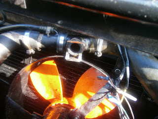 ... and then push the switch into the grommet. The switch pipe needs to be positioned so that water inside will cover the switch so this means the switch should be mounted horizontally or downwards.
 Reconnect wiring (dielectric grease on contacts) and secure with a safety tie.

So with trepidation I fired up the motor and let it warm up. Using an infra-red thermometer I monitored the temperature of the switch pipe. Whoppeee!! The fan operated around 80 deg C. I did also test my old switch in a cup of hot water- and I'm pleased to say it really was dud.
This is the last "fitting" job I had to do on the car before MOT- I still need to refine my carb setting and this really needs a road test: The trouble is that the law in the UK doesn't permit any road testing so the first time I can drive it will be en route to the testing station and that's really a bit late for a shake out. There is also the small question of whether I will actually get there!! I find myself doing little jobs- like putting screenwash in the water bottle! Probably in an attempt to put off the dreaded MOT test. Ah well - if it was easy we would all drive Lotuses.
I had intended to upgrade to the screw-in switch used in later Excels and bought the appropriate switch pipe from Lotusbits. Unfortunately this lacks the water return spigot because in later cars this was incorporated into the radiator bottom hose. Consequently this upgrade would mean a complete drain down and a new hose. I therefore postponed this mod until I next drain the system and ordered a replacement for the push-in type of Otter switch currently fitted. I know that these can fail but they are widely used... my MGB has one for instance, and they don't always fail so I will stick with it for the moment.
I don't want to drain the system- partly because it would waste the fluid, but also because its quite difficult to do- I struggled for some time with the drain plug last time although admittedly that was in the cold and dark which has coloured my memory! I decided therefore to preserve as much fluid as I could- and this should be possible since the switch is located relatively high up in the coolant system.
Fluid can only flow out if air can flow in to replace it so I blocked off the filler cap with a couple of sheets of clingfilm below the cap. The system should then be sealed and air pressure should hold most of the fluid inside.


So with trepidation I fired up the motor and let it warm up. Using an infra-red thermometer I monitored the temperature of the switch pipe. Whoppeee!! The fan operated around 80 deg C. I did also test my old switch in a cup of hot water- and I'm pleased to say it really was dud.
This is the last "fitting" job I had to do on the car before MOT- I still need to refine my carb setting and this really needs a road test: The trouble is that the law in the UK doesn't permit any road testing so the first time I can drive it will be en route to the testing station and that's really a bit late for a shake out. There is also the small question of whether I will actually get there!! I find myself doing little jobs- like putting screenwash in the water bottle! Probably in an attempt to put off the dreaded MOT test. Ah well - if it was easy we would all drive Lotuses.
Tuesday, 4 April 2017
Replacement door latch?
You may recall that I had received a duff latch as a replacement part from Lotusbits. Although they kindly swapped this for another, they didn't want the old one back which was great as I thought that I thought something inside might be useful, so I dismantled it to see if it could be repaired/salvaged.
New Replacement latch as received -
The central rivet has been replaced but this doesn't seem to have been strong enough- or perhaps nothing fitted properly in this bent state, because a screw has been driven into the latch body forcing the plate over a little.
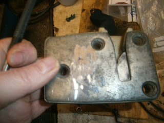 Remove latch cover
I removed both plates from the rear of the latch and carefully hammered both back into shape. I also had to file the plastic where the bodger's screw had been inserted before the plates would lie flat.
I reassembled the latch, its pretty much as in my previous post on my repair of the latch that came with the car described here, but in order to help with reassembly I now present several views of the plates and how they are arranged.
Note:
1. The cross link fits into the slotted cutout on the internal handle plate.
2. The cresent plate on this side is positioned pointing to the bottom of the lock, the smooth end is free and the notched end points in towards the plastic body

I firmly believe that there is a difference between a circlip, a snap ring and an E clip. These are E clips and have the internal flaps, circlips have a smooth contour and two eyes for opening them with pliers and a snap ring is a simple bent wire hoop - well in my view anyway. I don't like to see these confused- and for that matter split pins are not cotter pins! All this irritates me a bit... sorry rant over! Anyway- the latch uses E clips and I need to replace one retaining the rod (top right). I have a pack of the usual sizes but none fitted so I compressed one into position as a temporary measure and investigated. This clip is now de-listed by Lotus (not sure why) but apparently E clips are specified by the diameter of the shaft, not the groove into which they fit. This means I need 4.8mm or 3/16" E clips and these are readily available so I ordered a few.
I swapped the E clip when the right size came. The latch was functional now so I've stored it as a spare.
New Replacement latch as received -
 |
| "new latch" plate bent |
 |
| Cross link visible under the back plate... and loose- it should be hidden! |
The central rivet has been replaced but this doesn't seem to have been strong enough- or perhaps nothing fitted properly in this bent state, because a screw has been driven into the latch body forcing the plate over a little.
 |
| New screw added to bodge everything into position and hold the top of the plate down. |
 |
| Grind off head of replacement rivet |

 |
| Innards in correct location-Hook latch and circular latch undisturbed |
 |
| Rocking latch spring broken/misplaced |
 |
| Spring removed and trimmed to a better length |
 |
| Other side of latch- plates in position but very bent. |
 |
| Hook plate orientation relevant to circular latch. Note pin on hook plate that penetrates through the plastic (top left) to fit into the footplate on the other side. |
 |
| Spring below Latch note installed with bend towards centre. The latch itself rotates in the left hand groove below the spring. |
 |
| Foot plate was cracked so I re-welded and ground back down to shape. It still seems to be a little loose vertically and could perhaps lift off the pin from the hook latch. It seems to be OK at present though. I will investigate whether the footplate can be thickened on top without catching in the plastic body |
Note:
1. The cross link fits into the slotted cutout on the internal handle plate.
2. The cresent plate on this side is positioned pointing to the bottom of the lock, the smooth end is free and the notched end points in towards the plastic body
 |
| Handle lock plate correctly positioned- cross link held beneath plate. Temporary bolt holding latch together |
 |
| Key lock Z plate. The tab at the bottom (attached to cross link) is the lock and will slip into the space above the footplate when the door is closed. It will not lock unless the circular latch has been turned to the closed position- in this pic it is in the open configuration and so there is no room for the lock plate to fit- it jams on the footplate (top centre).- note the blob of weld where I had to repair this plate too.- the blob doesn't get in the way so I left it. |
 |
| Here the latch has been moved to the closed configuration. This withdraws the footplate and allows the locking plate to drop in beside it thus blocking its movement back up. |

 |
| Key lock plate- distorted E clip bent into place temporarily top right (later replaced with 4.8mm E clip) |
I swapped the E clip when the right size came. The latch was functional now so I've stored it as a spare.
Thursday, 30 March 2017
Passenger's door handle.
I have had a lot of trouble with both the handle and the latch on the passenger side of this car. I fixed the latch as described, but the handle suffered from the usual pulling out/stripping of the threads for the mounting bolts. Other handles used much more successful centrally mounted 4-bolt clips but the early Excel handles at least mounted through just two bolts fitting into captive metal inserts at each end of the handle. These don't last! Usually the inserts pull out or strip. When minepulled out I did try re-tapping the socket but that pulled out too so in the end I drilled it through and refitted using a nut and through bolt. Ugly but effective, at least while I was working on the rest of the car which presented far more serious problems. However I don't want to MOT it like this- and obviously its not going to be secure if the car were ever again to be legally mobile! I ordered a replacement handle from Lotusbits. I was warned that this comes with a repair which turned out to be relatively simple and I wish I had thought of it before drilling my own handle! I will try to rectify my own damaged handle as a spare using this method- which I describe below; but I will swap it for this better condition replacement. The replacement handle comes without a lock barrel and so will need to have that inserted. I also ordered a replacement door latch- I don't really need one of these because my old one is working satisfactorily after my repair, but I thought if I could get one that had not failed in the first place then this must be an improvement. I was very pleased with the handle (assuming that the Lotusbits repair holds) but less so with the latch.
Excel/Elite lock barrels
I have acquired 3 spare handles from Elite and Eclat. Two of these have matching lock barrels + keys although one of these has a damaged handle tab. This is a shame since these are the later silky-black tabs which would probably be very much in demand. None of these handles fit the Excel (too short) but since I need to insert a new lock barrel into my replacement handle, I removed the barrel from one of these to see if it would fit. The description is below... but in fact it doesn't!
 |
| My collection of Excel and Eclat door handles! |
The back of the handles doesn't look the same, but I did wonder if the lock barrel would be the same so I set about removing the barrel. The first step is to remove the lock actuating lever which is held on by a "C" clip.
 |
| Ease back the "C" clip and this releases the lock actuating arm |
 |
| Eclat switch with mounting clamp and lock barrel- easing back the C washer holding the lock arm. |
 |
| which can then be lifted off to release... |
 |
| ... the spacer washer and crimped washer beneath, "C" washer on left |
 |
| The lock barrel then taps out |
 |
| and can be released |
Excel Door Handle and Lock Barrel
This is the new (replacement) handle received from Lotus bits. Its been repaired using M6 nutserts fixed in place with Araldite. I think they are expanded enough in the Araldite to create a bulge that allows the compound to cling to the vertical sides above and below but not enough to crack the handle. Good trick! I may try this on my original handle.
The replacement lacks a lock barrel and since the Eclat and Elite are incompatible I need to swap the lock from my old handle. But I will add at this stage that it is possible to get a new lock barrel if you need one, but they are getting hard to find. I decided to lay one in in case this repair fails, and I got one of the few left at Kelvedon. However these are a Toyota part no 69051-14090 and are more plentiful abroad under that number. Hefty postage tho! The new lock comes with the radius arm and rod-locking clip already fitted. However, at this stage I had been assuming that the lock barrel would be just that; a cylindrical barrel inserted into the assembly like that in the Elite locks above. This would mean removing the attachments at the top and then pushing out the cylinder as before. If so the the first step would be to remove the lock actuating lever*. I had previously re-built this with weld so that it fitted the lock barrel. I did try this and removed both radius lever and spring- but it turned out to be completely unnecessary and in fact the lock is held on by just the one big and obvious screw... duhhh! Luckily it goes back together easily.

| Original handle with lock barrel and lock actuating arm. Note large screw which holds the lock in place- for some reason I had assumed removing the lock would be tricky and so didn't try this until after I'd tried removing the spring and actuating arm! |
It looks like this handle would have a cylindrical barrel as the Elite above. However it doesn't. Surprisingly its not necessary to remove the spring or actuating lever at all and the lock barrel assembly is simply released with the single large and obvious screw(!)...
Fitting both latch and door handle were as described previously EXCEPT that I encountered two problems with the handle and its new inserts:
Firstly, it is really important that the threaded inserts are pushed into the handle to the correct height when making the repair! The handle mounting clip rests on the top of the nutsert, and in my car in both doors, the mounting bracket also rests on top of the lock barrel mounting screw-head. There is however an obvious hole in the mounting bracket that coincides with the position of this screw, and the parts manual mentions (but does not illustrate) a spacer that could be fitted under the bracket here to make up the difference in height and allow the mounting bracket to be secured by both screws- resting on the tops of the nutsert and spacer.
Since I didn't have any such spacer I tried to fit the bracket in the same way as before. Sadly, I found that I just couldn't get the rear side of the handle to clamp firmly against the door skin. This turned out to be because the nutsert had been left too high such that the body clamp was too far away from the door skin when the mounting screw was tight. In fact there was nearly a 6mm gap between the clamp and the door handle frame when the screw was fully tightened, whilst the GRP of the door skin is only some 3.5mm thick.
Consequently it proved impossible to clamp the handle onto the door. The other end of the door was fitted with my home-made clamp and this had a deeper edge profile and so still tightened successfully.
There were obviously two courses of action here: I could file or grind the nutsert to lower the mounting position of the clip and, bring it closer to the door handle frame; or I could thicken the clip's locating edge. In the event I chose the latter, largely because I didn't want to do anything that might loosen the newly-inserted nutsert and both heat and vibration might do that. I cut a strip of packing metal and welded it onto the outside clamping edge of the clip. This narrowed the gap between clip and handle frame to 2mm which should allow it to clamp onto the door skin.
The second point is that the threaded section of the Nutsert is much shorter than the original threaded insert. There is also a build up of adhesive at the bottom of the hole and both of these points mean that the original mounting bolts (M6 16mm) are now needlessly too long. I replaced them with 10mm Allen button screws as these should be easier to tighten, and checked that they would both screw in fully without obstructing the movement of the handle.
The door handle now installed properly and tightened up flush against the door skin. When fitting the door handle I found the following really helped.
1. Fit the rear mounting bracket to the door handle loosely before offering the handle up to the door.
2.Drill a small hole in the inner door skin opposite the rear bracket mounting screw so that you can insert a small socket or in my case an Allen driver straight in to tighten.
3. Fit the forward bracket once the handle is held loosely by the rear clamp. There is straight access to this mounting bolt.
4. It is difficult to adjust the exterior handle actuating rod lengths because they are hard to screw in/out of their adjusters. Angle the rods forward as far as they can go (down against the beam) and there is just room to rotate them there in position instead of continually releasing the latch.
5. When fitting the door opening rod to the interior handle (lower rod), open the handle slightly to provide room to swivel the plastic lock round the rod.
Rod Adjustment
The WM pretends that rod adjustment is a logical and predictable procedure.Do not be fooled, it is not! The lock is the product of a deranged mind and is the spawn of the Devil- If you don't expect it to be easy it will not disappoint!
This is what I did and it might work for you.
Firstly make sure everything works outside the door. I say this because even with a new lock it appears to be possible to get the singals crossed and the latch will not then lock- so make sure its in a lockable configuration before starting.
The circular latch on the side of the door has two positions, open and closed. This is "open"- ready to receive the hasp on the B pillar. The door will not lock like this so slide the latch closed by pushing a screwdriver into the inviting slot (!) and the latch will clip to the closed configuration.

...and this is closed (different latch tho)

If all is well in this position you will be able to lock the latch. The latch is operated by 4 rods; in clockwise order from the front I'm calling these rods 1-4. Rods 1 and 3 operate the lock, rods 2 and 4 operate the latch to open the door. Rod 1 is attached to the exterior key-lock radius lever, rod 2 to the exterior handle. Rod 3 is attached to the interior locking handle and rod 4 to the interior opening handle. If the latch is set up right then pulling/pushing on the relevant rods will achieve the desired effect. The lock operates by moving a locking tab attached to the external side of the cross-rod. This is visible below.

When the door is closed operating either locking rod will flip this tab (visible above) downwards besides the sliding latch footplate and this will prevent it from sliding upwards to open the door. If you find that this tab will not fit in front of the sliding footplate the lock is in the wrong conformation. Operate the latch handles and switch between open/closed configurations until everything is in position and the locks operate easily. When it is right, lock operation requires little force and is a positive location. If you've got this right then put the latch in the closed configuration operate the lock and insert the mechanism into the door- remember to guide the longer rods through the slot in the middle of the door and the shorter rods up and out through the opening of the door beam as you do so. Fit the latch loosely to the side of the door. You can then (just) see the operating points of rods 1 and 2 through the cutout in the door.

Check that the door is in the closed position and that the lock still operates easily. Fit rod 1 first. The door is locked so this rod should fit into the key radius arm fully depressed (ie at the bottom of its slot) when the key is rotated to move the arm down. Make sure it fits here easily and without strain. I found it wasnt worth worrying about whether the key returns or not because at this stage it may not.
The WM manual gives a sort of useful diagram- rod X is rod 1 in
my scheme. Note the locking lever is down beside the footplate. If you turn the key you should get full travel up the mounting slot by rod 1 and unlocking the door.

Rod 2 needs to be installed in position A as shown in the diagram- this is at the base of the upper vertical slot of the "Z" profile but on a level with the cross slot of the "Z" ... BUT it will only be at point A when the door is locked and the tab handle on the exterior is operated. Releasing the tab handle will pull it up the left hand slot of the Z profile.
Check that you can unlock the door with the key- as you do so rod 2 will slip across the horizontal slot in the "Z" profile to point B. In this position operating the exterior tab handle will pull the whole metal plate upwards and operate the latch to open the door. I don't mean the latch will move- it won't, but it will be released such that it can pull off the B pillar hasp- or if you've are testing it with the door open, you can now flip it to the open profile with the screwdriver you had used earlier to close it. If rod 2 cannot slip across the horizontal slot (A to B) in the "Z" profile its probably too high (ie rod too short) so elongate it by a few turns and try again. Eventually the movement of rod 2 should require little force and occur in concert with rod 1 operation. Remember you can only lock and unlock when the door circular latch is closed.
You now need to fit rods 3 and 4- and although these are much easier there is a possibility of getting them fighting with rods 1 and 2 rather than working in concert. If this happens disconnect them and operate the latch a few times to make sure that you can still lock easily with rod 1 and that rod 2 still moves as it should. I attached rod 3 first- again with the door locked. I flipped the interior locking tab to the locked position and offered up the rod, adjusting its length by screwing in or out until it entered the fastening without strain. Operating the interior locking tab should then lock and unlock the door by operating the locking tab via the cross rod. Locking with the key should move the interior licking tab again through the cross rod.
Unlock the door and set the door latch to the closed configuration and then adjust rod 4 to fit without strain into its attachment on the the interior door opening handle. As you pull the interior handle the circular latch will be released (again it wont move, just release) so that you can flip the door side latch between open and closed.
It was my experience that every time I set one rod I seemed to upset the setting on one that had been adjusted earlier so you do have to keep revisiting the adjustments until you get something that works. I found that unlocking with the key remained problematic- it works fine but I have to press the door inwards as I unlock. I don't know why this is but hey- its working so I was happy to leave it there and refit the door card and handle trim.
Latch
I was less pleased with the latch that I received- unlike the handle this wasn't identified as having been repaired, but it has clearly been taken apart and put back together previously and- although I don't like to make a big thing of it- it simply hasn't been done as well as my own effort! The rear plate is bent, one side plate is bent and the cross link is loose- in fact its threatening to fall out of the latch.
The central rivet has been replaced but this doesn't seem to have been strong enough- or perhaps nothing fitted properly in this bent state, because a screw has been driven into the latch body forcing the plate over a little.
Overall I'm not pleased and this part was destined to go back!- In fact Lotusbits were very apologetic on the phone and agreed to send a better latch and didn't need me to return this defunct one. Great for me, saves postage and hopefully some of the latch internals will be ok and might be useful one day! Good service I think!!- Well in theory; in fact it took nearly 2 weeks for the replacement to come and this turned out to be lacking a rear actuating plate that had to be swapped from the old latch - so very much a case of "some assembly required". Since it seems unavoidable to mend one of these two replacements I will have a go at repairing the duff latch above just in case its feasible. I will put the outcome in a separate post.
 |
| Undo screw to release lock barrel |
 |
| Lock barrel retaining screw and anti-shake washer. |
... and it installs into the new handle just as easily. To guard against loosening of the lock actuating arm which had happened previously I fixed it using two "E" washers to better fill the locating groove.
 |
| Original lock barrel installed in Lotusbits repaired replacement handle. Plastic rod-clip missing from door lever at this stage |
I needed to swap the plastic rod clip from my old to the new handle lever as this was missing in the new handle. Squeeze the back together and it pulls out.
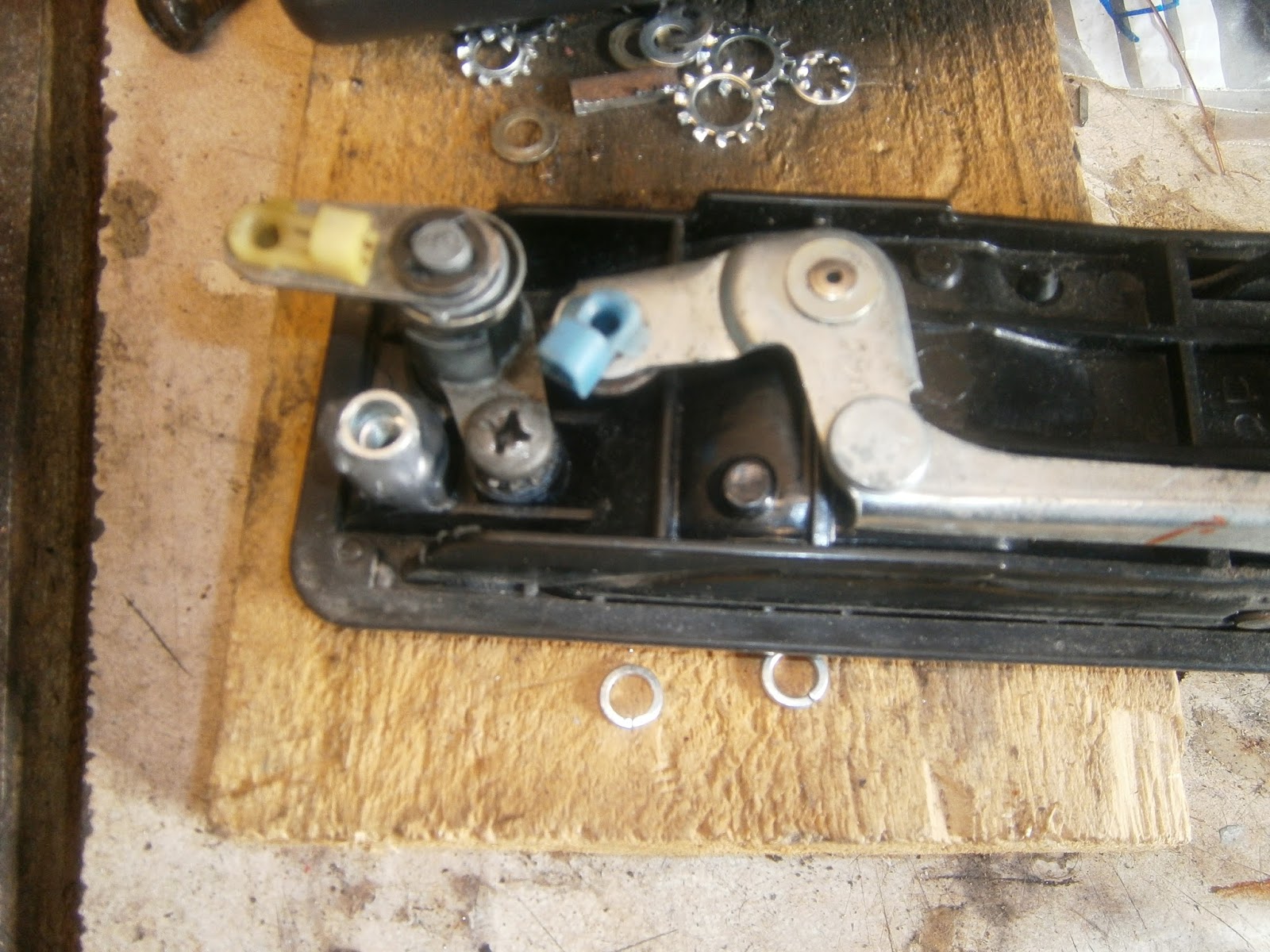 |
| Rod locking clip installed. |
Firstly, it is really important that the threaded inserts are pushed into the handle to the correct height when making the repair! The handle mounting clip rests on the top of the nutsert, and in my car in both doors, the mounting bracket also rests on top of the lock barrel mounting screw-head. There is however an obvious hole in the mounting bracket that coincides with the position of this screw, and the parts manual mentions (but does not illustrate) a spacer that could be fitted under the bracket here to make up the difference in height and allow the mounting bracket to be secured by both screws- resting on the tops of the nutsert and spacer.
Since I didn't have any such spacer I tried to fit the bracket in the same way as before. Sadly, I found that I just couldn't get the rear side of the handle to clamp firmly against the door skin. This turned out to be because the nutsert had been left too high such that the body clamp was too far away from the door skin when the mounting screw was tight. In fact there was nearly a 6mm gap between the clamp and the door handle frame when the screw was fully tightened, whilst the GRP of the door skin is only some 3.5mm thick.
 |
| Excess (6.5mm) gap between handle frame and rear clamp when the clamp is fully tightened. |
Consequently it proved impossible to clamp the handle onto the door. The other end of the door was fitted with my home-made clamp and this had a deeper edge profile and so still tightened successfully.
 |
| Home-made forward clamp- closes up well against the handle frame. |
 |
| Extre strip of steel welded onto clamp as packer. |
 |
| Modified clamp in position- packing steel takes up the excess gap. |
The door handle now installed properly and tightened up flush against the door skin. When fitting the door handle I found the following really helped.
1. Fit the rear mounting bracket to the door handle loosely before offering the handle up to the door.
2.Drill a small hole in the inner door skin opposite the rear bracket mounting screw so that you can insert a small socket or in my case an Allen driver straight in to tighten.
3. Fit the forward bracket once the handle is held loosely by the rear clamp. There is straight access to this mounting bolt.
4. It is difficult to adjust the exterior handle actuating rod lengths because they are hard to screw in/out of their adjusters. Angle the rods forward as far as they can go (down against the beam) and there is just room to rotate them there in position instead of continually releasing the latch.
5. When fitting the door opening rod to the interior handle (lower rod), open the handle slightly to provide room to swivel the plastic lock round the rod.
Rod Adjustment
The WM pretends that rod adjustment is a logical and predictable procedure.Do not be fooled, it is not! The lock is the product of a deranged mind and is the spawn of the Devil- If you don't expect it to be easy it will not disappoint!
This is what I did and it might work for you.
Firstly make sure everything works outside the door. I say this because even with a new lock it appears to be possible to get the singals crossed and the latch will not then lock- so make sure its in a lockable configuration before starting.
The circular latch on the side of the door has two positions, open and closed. This is "open"- ready to receive the hasp on the B pillar. The door will not lock like this so slide the latch closed by pushing a screwdriver into the inviting slot (!) and the latch will clip to the closed configuration.

...and this is closed (different latch tho)

If all is well in this position you will be able to lock the latch. The latch is operated by 4 rods; in clockwise order from the front I'm calling these rods 1-4. Rods 1 and 3 operate the lock, rods 2 and 4 operate the latch to open the door. Rod 1 is attached to the exterior key-lock radius lever, rod 2 to the exterior handle. Rod 3 is attached to the interior locking handle and rod 4 to the interior opening handle. If the latch is set up right then pulling/pushing on the relevant rods will achieve the desired effect. The lock operates by moving a locking tab attached to the external side of the cross-rod. This is visible below.
 |
| Locking tab on cross rod. Rod 1 is visible left threaded into its trunnion in the single locking slot, rod 2 threads into its trunnion in the "Z" profile at the top. The locking tab is centre and shown here in the raised (unlocked) position. If the cross rod is folded towards the right in this picture then the tab will be lowered above and beside the sliding footplate which isn't terribly clear here. It extends below the spacer piece from the pin at the right hand side to the shiny part visible in the centre.- It may be clearer below |

When the door is closed operating either locking rod will flip this tab (visible above) downwards besides the sliding latch footplate and this will prevent it from sliding upwards to open the door. If you find that this tab will not fit in front of the sliding footplate the lock is in the wrong conformation. Operate the latch handles and switch between open/closed configurations until everything is in position and the locks operate easily. When it is right, lock operation requires little force and is a positive location. If you've got this right then put the latch in the closed configuration operate the lock and insert the mechanism into the door- remember to guide the longer rods through the slot in the middle of the door and the shorter rods up and out through the opening of the door beam as you do so. Fit the latch loosely to the side of the door. You can then (just) see the operating points of rods 1 and 2 through the cutout in the door.

Check that the door is in the closed position and that the lock still operates easily. Fit rod 1 first. The door is locked so this rod should fit into the key radius arm fully depressed (ie at the bottom of its slot) when the key is rotated to move the arm down. Make sure it fits here easily and without strain. I found it wasnt worth worrying about whether the key returns or not because at this stage it may not.
The WM manual gives a sort of useful diagram- rod X is rod 1 in
my scheme. Note the locking lever is down beside the footplate. If you turn the key you should get full travel up the mounting slot by rod 1 and unlocking the door.

Rod 2 needs to be installed in position A as shown in the diagram- this is at the base of the upper vertical slot of the "Z" profile but on a level with the cross slot of the "Z" ... BUT it will only be at point A when the door is locked and the tab handle on the exterior is operated. Releasing the tab handle will pull it up the left hand slot of the Z profile.
Check that you can unlock the door with the key- as you do so rod 2 will slip across the horizontal slot in the "Z" profile to point B. In this position operating the exterior tab handle will pull the whole metal plate upwards and operate the latch to open the door. I don't mean the latch will move- it won't, but it will be released such that it can pull off the B pillar hasp- or if you've are testing it with the door open, you can now flip it to the open profile with the screwdriver you had used earlier to close it. If rod 2 cannot slip across the horizontal slot (A to B) in the "Z" profile its probably too high (ie rod too short) so elongate it by a few turns and try again. Eventually the movement of rod 2 should require little force and occur in concert with rod 1 operation. Remember you can only lock and unlock when the door circular latch is closed.
You now need to fit rods 3 and 4- and although these are much easier there is a possibility of getting them fighting with rods 1 and 2 rather than working in concert. If this happens disconnect them and operate the latch a few times to make sure that you can still lock easily with rod 1 and that rod 2 still moves as it should. I attached rod 3 first- again with the door locked. I flipped the interior locking tab to the locked position and offered up the rod, adjusting its length by screwing in or out until it entered the fastening without strain. Operating the interior locking tab should then lock and unlock the door by operating the locking tab via the cross rod. Locking with the key should move the interior licking tab again through the cross rod.
Unlock the door and set the door latch to the closed configuration and then adjust rod 4 to fit without strain into its attachment on the the interior door opening handle. As you pull the interior handle the circular latch will be released (again it wont move, just release) so that you can flip the door side latch between open and closed.
It was my experience that every time I set one rod I seemed to upset the setting on one that had been adjusted earlier so you do have to keep revisiting the adjustments until you get something that works. I found that unlocking with the key remained problematic- it works fine but I have to press the door inwards as I unlock. I don't know why this is but hey- its working so I was happy to leave it there and refit the door card and handle trim.
 |
| Please with result- handle fits well... and it works! |
I was less pleased with the latch that I received- unlike the handle this wasn't identified as having been repaired, but it has clearly been taken apart and put back together previously and- although I don't like to make a big thing of it- it simply hasn't been done as well as my own effort! The rear plate is bent, one side plate is bent and the cross link is loose- in fact its threatening to fall out of the latch.
|
| "new latch" plate bent |
 |
| After repair mine sits flat in position in the plastic body |
|
| Cross link visible and loose- it should be hidden! |
The central rivet has been replaced but this doesn't seem to have been strong enough- or perhaps nothing fitted properly in this bent state, because a screw has been driven into the latch body forcing the plate over a little.
|
| New screw added to bodge everything into position and hold the top of the plate down. |
Subscribe to:
Posts (Atom)