I have had a lot of trouble with both the handle and the latch on the passenger side of this car. I fixed the latch as described, but the handle suffered from the usual pulling out/stripping of the threads for the mounting bolts. Other handles used much more successful centrally mounted 4-bolt clips but the early Excel handles at least mounted through just two bolts fitting into captive metal inserts at each end of the handle. These don't last! Usually the inserts pull out or strip. When minepulled out I did try re-tapping the socket but that pulled out too so in the end I drilled it through and refitted using a nut and through bolt. Ugly but effective, at least while I was working on the rest of the car which presented far more serious problems. However I don't want to MOT it like this- and obviously its not going to be secure if the car were ever again to be legally mobile! I ordered a replacement handle from Lotusbits. I was warned that this comes with a repair which turned out to be relatively simple and I wish I had thought of it before drilling my own handle! I will try to rectify my own damaged handle as a spare using this method- which I describe below; but I will swap it for this better condition replacement. The replacement handle comes without a lock barrel and so will need to have that inserted. I also ordered a replacement door latch- I don't really need one of these because my old one is working satisfactorily after my repair, but I thought if I could get one that had not failed in the first place then this must be an improvement. I was very pleased with the handle (assuming that the Lotusbits repair holds) but less so with the latch.
Excel/Elite lock barrels
I have acquired 3 spare handles from Elite and Eclat. Two of these have matching lock barrels + keys although one of these has a damaged handle tab. This is a shame since these are the later silky-black tabs which would probably be very much in demand. None of these handles fit the Excel (too short) but since I need to insert a new lock barrel into my replacement handle, I removed the barrel from one of these to see if it would fit. The description is below... but in fact it doesn't!
 |
| My collection of Excel and Eclat door handles! |
The back of the handles doesn't look the same, but I did wonder if the lock barrel would be the same so I set about removing the barrel. The first step is to remove the lock actuating lever which is held on by a "C" clip.
 |
| Ease back the "C" clip and this releases the lock actuating arm |
 |
| Eclat switch with mounting clamp and lock barrel- easing back the C washer holding the lock arm. |
 |
| which can then be lifted off to release... |
 |
| ... the spacer washer and crimped washer beneath, "C" washer on left |
 |
| The lock barrel then taps out |
 |
| and can be released |
I found these parts were incompatible with the Excel lock so I put it back together... Reassembly is the reverse.
Excel Door Handle and Lock Barrel
This is the new (replacement) handle received from Lotus bits. Its been repaired using M6 nutserts fixed in place with Araldite. I think they are expanded enough in the Araldite to create a bulge that allows the compound to cling to the vertical sides above and below but not enough to crack the handle. Good trick! I may try this on my original handle.
The replacement lacks a lock barrel and since the Eclat and Elite are incompatible I need to swap the lock from my old handle. But
I will add at this stage that it is possible to get a new lock barrel if you need one, but they are getting hard to find. I decided to lay one in in case this repair fails, and I got one of the few left at Kelvedon. However these are a Toyota part no 69051-14090 and are more plentiful abroad under that number. Hefty postage tho! The new lock comes with the radius arm and rod-locking clip already fitted. However, at this stage I had been assuming that the lock barrel would be just that; a cylindrical barrel inserted into the assembly like that in the Elite locks above. This would mean removing the attachments at the top and then pushing out the cylinder as before. If so the the first step would be to
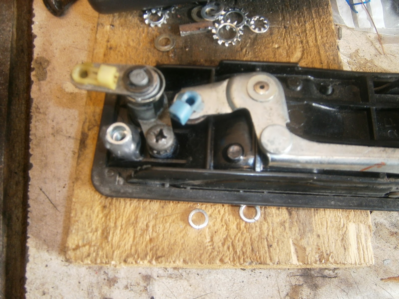
remove the lock actuating lever*. I had previously re-built this with weld so that it fitted the lock barrel. I did try this and removed both radius lever and spring- but it turned out to be completely unnecessary and in fact the lock is held on by just the one big and obvious screw... duhhh! Luckily it goes back together easily.
|
| Original handle with lock barrel and lock actuating arm. Note large screw which holds the lock in place- for some reason I had assumed removing the lock would be tricky and so didn't try this until after I'd tried removing the spring and actuating arm! |
It looks like this handle would have a cylindrical barrel as the Elite above. However it doesn't. Surprisingly its not necessary to remove the spring or actuating lever at all and the lock barrel assembly is simply released with the single large and obvious screw(!)...
 |
| Undo screw to release lock barrel |
 |
| Lock barrel retaining screw and anti-shake washer. |
... and it installs into the new handle just as easily. To guard against loosening of the lock actuating arm which had happened previously I fixed it using two "E" washers to better fill the locating groove.
 |
| Original lock barrel installed in Lotusbits repaired replacement handle. Plastic rod-clip missing from door lever at this stage |
I needed to swap the plastic rod clip from my old to the new handle lever as this was missing in the new handle. Squeeze the back together and it pulls out.
 |
| Rod locking clip installed. |
Fitting both latch and door handle were as described previously EXCEPT that I encountered two problems with the handle and its new inserts:
Firstly, it is really important that the threaded inserts are pushed into the handle to the correct height when making the repair! The handle mounting clip rests on the top of the nutsert, and in my car in both doors, the mounting bracket also rests on top of the lock barrel mounting screw-head. There is however an obvious hole in the mounting bracket that coincides with the position of this screw, and the parts manual mentions (but does not illustrate) a spacer that could be fitted under the bracket here to make up the difference in height and allow the mounting bracket to be secured by both screws- resting on the tops of the nutsert and spacer.
Since I didn't have any such spacer I tried to fit the bracket in the same way as before. Sadly, I found that I just couldn't get the rear side of the handle to clamp firmly against the door skin. This turned out to be because the nutsert had been left too high such that the body clamp was too far away from the door skin when the mounting screw was tight. In fact there was nearly a 6mm gap between the clamp and the door handle frame when the screw was fully tightened, whilst the GRP of the door skin is only some 3.5mm thick.
 |
| Excess (6.5mm) gap between handle frame and rear clamp when the clamp is fully tightened. |
Consequently it proved impossible to clamp the handle onto the door. The other end of the door was fitted with my home-made clamp and this had a deeper edge profile and so still tightened successfully.
 |
| Home-made forward clamp- closes up well against the handle frame. |
There were obviously two courses of action here: I could file or grind the nutsert to lower the mounting position of the clip and, bring it closer to the door handle frame; or I could thicken the clip's locating edge. In the event I chose the latter, largely because I didn't want to do anything that might loosen the newly-inserted nutsert and both heat and vibration might do that. I cut a strip of packing metal and welded it onto the outside clamping edge of the clip. This narrowed the gap between clip and handle frame to 2mm which should allow it to clamp onto the door skin.
 |
| Extre strip of steel welded onto clamp as packer. |
 |
| Modified clamp in position- packing steel takes up the excess gap. |
The second point is that the threaded section of the Nutsert is much shorter than the original threaded insert. There is also a build up of adhesive at the bottom of the hole and both of these points mean that the original mounting bolts (M6 16mm) are now needlessly too long. I replaced them with 10mm Allen button screws as these should be easier to tighten, and checked that they would both screw in fully without obstructing the movement of the handle.
The door handle now installed properly and tightened up flush against the door skin. When fitting the door handle I found the following really helped.
1. Fit the rear mounting bracket to the door handle loosely before offering the handle up to the door.
2.Drill a small hole in the inner door skin opposite the rear bracket mounting screw so that you can insert a small socket or in my case an Allen driver straight in to tighten.
3. Fit the forward bracket once the handle is held loosely by the rear clamp. There is straight access to this mounting bolt.
4. It is difficult to adjust the exterior handle actuating rod lengths because they are hard to screw in/out of their adjusters. Angle the rods forward as far as they can go (down against the beam) and there is just room to rotate them there in position instead of continually releasing the latch.
5. When fitting the door opening rod to the interior handle (lower rod), open the handle slightly to provide room to swivel the plastic lock round the rod.
Rod Adjustment
The WM pretends that rod adjustment is a logical and predictable procedure.Do not be fooled, it is not! The lock is the product of a deranged mind and is the spawn of the Devil- If you don't expect it to be easy it will not disappoint!
This is what I did and it might work for you.
Firstly make sure everything works outside the door. I say this because even with a new lock it appears to be possible to get the singals crossed and the latch will not then lock- so make sure its in a lockable configuration before starting.
The circular latch on the side of the door has two positions, open and closed. This is "open"- ready to receive the hasp on the B pillar. The door will not lock like this so slide the latch closed by pushing a screwdriver into the inviting slot (!) and the latch will clip to the closed configuration.

...and this is closed (different latch tho)
If all is well in this position you will be able to lock the latch. The latch is operated by 4 rods; in clockwise order from the front I'm calling these rods 1-4. Rods 1 and 3 operate the lock, rods 2 and 4 operate the latch to open the door. Rod 1 is attached to the exterior key-lock radius lever, rod 2 to the exterior handle. Rod 3 is attached to the interior locking handle and rod 4 to the interior opening handle. If the latch is set up right then pulling/pushing on the relevant rods will achieve the desired effect. The lock operates by moving a locking tab attached to the external side of the cross-rod. This is visible below.
 |
| Locking tab on cross rod. Rod 1 is visible left threaded into its trunnion in the single locking slot, rod 2 threads into its trunnion in the "Z" profile at the top. The locking tab is centre and shown here in the raised (unlocked) position. If the cross rod is folded towards the right in this picture then the tab will be lowered above and beside the sliding footplate which isn't terribly clear here. It extends below the spacer piece from the pin at the right hand side to the shiny part visible in the centre.- It may be clearer below |

When the door is closed operating either locking rod will flip this tab (visible above) downwards besides the sliding latch footplate and this will prevent it from sliding upwards to open the door. If you find that this tab will not fit in front of the sliding footplate the lock is in the wrong conformation. Operate the latch handles and switch between open/closed configurations until everything is in position and the locks operate easily. When it is right, lock operation requires little force and is a positive location. If you've got this right then put the latch in the closed configuration operate the lock and insert the mechanism into the door- remember to guide the longer rods through the slot in the middle of the door and the shorter rods up and out through the opening of the door beam as you do so. Fit the latch loosely to the side of the door. You can then (just) see the operating points of rods 1 and 2 through the cutout in the door.

Check that the door is in the closed position and that the lock still operates easily. Fit rod 1 first. The door is locked so this rod should fit into the key radius arm fully depressed (ie at the bottom of its slot) when the key is rotated to move the arm down. Make sure it fits here easily and without strain. I found it wasnt worth worrying about whether the key returns or not because at this stage it may not.
The WM manual gives a sort of useful diagram- rod X is rod 1 in
my scheme. Note the locking lever is down beside the footplate. If you turn the key you should get full travel up the mounting slot by rod 1 and unlocking the door.

Rod 2 needs to be installed in position A as shown in the diagram- this is at the base of the upper vertical slot of the "Z" profile but on a level with the cross slot of the "Z" ... BUT it will only be at point A when the door is locked and the tab handle on the exterior is operated. Releasing the tab handle will pull it up the left hand slot of the Z profile.
Check that you can unlock the door with the key- as you do so rod 2 will slip across the horizontal slot in the "Z" profile to point B. In this position operating the exterior tab handle will pull the whole metal plate upwards and operate the latch to open the door. I don't mean the latch will move- it won't, but it will be released such that it can pull off the B pillar hasp- or if you've are testing it with the door open, you can now flip it to the open profile with the screwdriver you had used earlier to close it. If rod 2 cannot slip across the horizontal slot (A to B) in the "Z" profile its probably too high (ie rod too short) so elongate it by a few turns and try again. Eventually the movement of rod 2 should require little force and occur in concert with rod 1 operation. Remember you can only lock and unlock when the door circular latch is closed.
You now need to fit rods 3 and 4- and although these are much easier there is a possibility of getting them fighting with rods 1 and 2 rather than working in concert. If this happens disconnect them and operate the latch a few times to make sure that you can still lock easily with rod 1 and that rod 2 still moves as it should. I attached rod 3 first- again with the door locked. I flipped the interior locking tab to the locked position and offered up the rod, adjusting its length by screwing in or out until it entered the fastening without strain. Operating the interior locking tab should then lock and unlock the door by operating the locking tab via the cross rod. Locking with the key should move the interior licking tab again through the cross rod.
Unlock the door and set the door latch to the closed configuration and then adjust rod 4 to fit without strain into its attachment on the the interior door opening handle. As you pull the interior handle the circular latch will be released (again it wont move, just release) so that you can flip the door side latch between open and closed.
It was my experience that every time I set one rod I seemed to upset the setting on one that had been adjusted earlier so you do have to keep revisiting the adjustments until you get something that works. I found that unlocking with the key remained problematic- it works fine but I have to press the door inwards as I unlock. I don't know why this is but hey- its working so I was happy to leave it there and refit the door card and handle trim.
 |
| Please with result- handle fits well... and it works! |
Latch
I was less pleased with the latch that I received- unlike the handle this wasn't identified as having been repaired, but it has clearly been taken apart and put back together previously and- although I don't like to make a big thing of it- it simply hasn't been done as well as my own effort! The rear plate is bent, one side plate is bent and the cross link is loose- in fact its threatening to fall out of the latch.
 |
| "new latch" plate bent |
 |
| After repair mine sits flat in position in the plastic body |
 |
| Cross link visible and loose- it should be hidden! |
The central rivet has been replaced but this doesn't seem to have been strong enough- or perhaps nothing fitted properly in this bent state, because a screw has been driven into the latch body forcing the plate over a little.
 |
| New screw added to bodge everything into position and hold the top of the plate down. |
Overall I'm not pleased and this part was destined to go back!- In fact Lotusbits were very apologetic on the phone and agreed to send a better latch and didn't need me to return this defunct one. Great for me, saves postage and hopefully some of the latch internals will be ok and might be useful one day! Good service I think!!- Well in theory; in fact it took nearly 2 weeks for the replacement to come and this turned out to be lacking a rear actuating plate that had to be swapped from the old latch - so very much a case of "some assembly required". Since it seems unavoidable to mend one of these two replacements I will have a go at repairing the duff latch above just in case its feasible. I will put the outcome in a separate post.