Search for tasks- type in keywords

Wednesday, 2 December 2015

Grinding (lapping) in the valves; fitting springs and stem seals

Having tried to grind in the valves manually, I did find that this was quite a lot of effort and very frustrating as the tool kept detaching from the valve heads (see my earlier post...). I therefore ordered a drill-mounted lapping  attachment. The one I went for was  German and made by BGS Werkzeug tools; its about half the price of the Gunson's EeZilap but seems just as robust-  It didn't come with any instructions but wasn't too tricky to work out how to use ...  and the Eezilap doesn't come with instructions either!
This is the German valve lapper. It comes with two different sized suckers to fit most valves.
The lapper should be used at a max rpm of 1200, I think 1000 is about fine. I measured the rpm of my hand held drill using a handheld rpm meter (a really neat and cheap piece of kit usable on the pillar and hand drills as well as the lathe and even the occasional engine!). My drill was giving 350 and 1100 rpm on speeds 1 and 2 respectively. I think it will spin faster with a newly charged battery but as it was the high speed was pretty much perfect. The lapping arrangement is similar to the manual process. I fitted a small spring on the valve stem to help it lift between grinding bouts. Remember to liberally lubricate the valve stem and guide, then apply some fine paste on the valve rim before lowering it into the guide and onto the seat.
Spring on valve stem to assist raising the head. Lubricate the stem with loads of engine oil.
Valve inserted with spring to raise head


The lapper then attaches with the sucker but make sure the drill is positioned in line with the valve stem lines... its easier to position the head with the valves you want to grind positioned furthest from you so that their stems are angled towards you and not as shown in this pic as grinding away from yourself as shown here does get quite tiring.


When the drill is operated the valve is rotated in one direction unless you hold the larger disc section when a reciprocating motion is induced. I found it was easy to take a fairly light grip on the disc section so that the drill tended to oscillate and then slip through the fingers to a new position and then oscillate again, slip again etc. etc. You can monitor the slippage positions by looking at the movement of the screw heads in the top of the attachment. This means you can ensure that the valve is lapped in evenly. I allowed it to slip about 25 degrees each time and went round the valve seat twice.
Loose grip on tool, monitor slippage by looking at the screw head on the top of the disc section.
Valve seat before lapping-  heavy pitting. I think its an "evens" contest as to whether grinding or a seat recut is best.


Same seat after lapping- great improvement- still not perfect but pretty good!

The final step after lapping all valves was to clean the head thoroughly. I removed all the studs so that the rings of crud around their bases could be easily scraped off and chased the threads on all studs with an M8 die nut. I bought some small bottle brushes to make sure the valve guides were clean and then washed the whole head in paraffin followed by carb cleaner. Lastly I gave everything a good blast through with an air line, including the stud holes where a surprisingly large amount of muck was hiding.

Refit the valves (adding assembly lube to the stems) and springs and hey- job done!  Now I need to finish the head that I've had serviced and then get on with the cam carriers!

I took the head to my local engineers- Southern Rebore Services who confirmed that all inlet valves and guides are fine and that only the exhaust valves/guides need to be replaced. They also examined and confirmed that the head does not require skimming for flatness and will therefore carry out only a "dressing skim" following guide replacement; in case the heating process employed during changing the guides should introduce a slight warping.
Head as returned from Southern Rebore... the original inlet valves (furthest from camera) weren't changed. These are higher than the new exhaust guides fitted closest to camera because...

These guides are designed to accept a valve stem seal. 
Stem seals weren't an original Lotus feature but they seem a really good idea, especially for the exhaust guides which owing to the canted over position of the motor tend to run surrounded by oil. If fitting stem seals you must fit the spring seat first as this wont go over the seal!

Light skim to bottom of head as received from S rebore.

Recut seats on exhaust valves.

Bit mystified by the second head. The inlet valves ground as expected right ac ross the margin of the valve and the full width of the seat. This was the same as observed with the head above. However the new exhaust valves in the recut seats ground only across the centre section of the valve margin and seat... see pic.

Inlet valve (front|) and exhaust valve (rear) showing the difference in ground surfaces.
This sort of behaviour is reminiscent of the triple angle seat cutting adopted in more modern motors, and not originally in the Lotus. I had asked for the seats to be cut as a single angle but this behaviour indicates that either they weren't... or perhaps the valves were already ground in the triple fashion around their edges. I will need to contact Southern Rebore and Kemp High Performnance to find out more about these points.

Well verdict from both was that yes this is a triple seat recut... shouldn't have been because the exhausts run hotter and so benefit from a good seat contact to the head to help dissipate the heat. However Kemp Racing confirm that overall this shouldn't make much of a practical difference if not a racing motor so advise its safe to go ahead and reassemble.

Inlet valves all fitted

As noted earlier- the new guides are lower than the lotus originals as they are made compatible with a stem oil seal.
Stem seal no 8.
These could be popped onto the valve guides by hand but in order to ensure that they went on straight and without damaging the rubber I used a seal installation kit- got thats econd hand on eBay at 5 quid and so a reasonable investment. I selected the installer that was about the same size as the valve stem and had a recess that accepted the seal
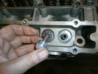
Installer tool head

... slip on the stem seal..

and position using hand pressure.
The carrier screws into the end of the drift
and can be used to tap the seal home, whilst the projection keeps everything in line. Note the gap at the base of the seal here

... and now the seal is tapped fully home
I applied red assembly lube to the tops of the valve seals and also the valve stems and inserted the valves from underneath. Here I was greatly assisted by using a Sealey head stand. This removes the need for two of the extra hands otherwise required  to hold the head whilst using the valve spring compressor.

Head on Sealey head stand. A useful pieces of kit- but actually easily made so I wouldn't recommend buying it.
The stand allowed me to use a more suitable valve spring compressor. An extra bonus was that the stem seals now gripped the valve stem so they didn't drop out as soon as you let go of them. This eliminated the need for the third extra hand reducing the number required in total to 2... and thus making the job feasible.
Draper valve spring compressor in use- I went for the largest version for ZETEC motors. Probably overkill as it was a little unwieldy- the next smallest would have been fine.


Friday, 30 October 2015

Decarbonizing the head

This is  a follow up to the cleaning the valves post and its my experience with the Utube recommended method from that post. https://www.youtube.com/watch?v=7GEmuQa3dPY

I used a brass wire brush fitted into a Dremell flexible shaft drive. Overall it worked well but the job really needs a beefier driving system. Mine is battery operated and kept stalling, needing a few moments to reconfigure.
Starting condition, exhausts (top) much dirtier than inlets

Dremell flexible drive

Brass brush fitted into drive.


The Dremmel works well on the valve seats, when using it be careful to avoid in-out motions that might score a line right across the seat- try and stick to circumferential movements. The seats cleaned up easily and very well, the brush was also useful for polishing minor blemishes off the alloy inside the chamber. It was also possible to try and get the carbon off the ports... this is a VERY messy job. Dremmel or no, there is no way of avoiding getting extremely dirty and spattering the stuff everywhere! I found liberal use of diesel EGR cleaner immediately followed by the Dremelling could swirl the cleaner around the port and help to loosen the carbon- but it comes off as a sticky paste- really Yukk!

Exhaust ports nearly done...

OK- well an observation- for effective decarbonising with a Dremmell- make sure its fully charged! Overnight on the charger helped the performance of mine no end!

Lapping (Grinding) in the valves.

This spare head isn't perfect but it seemed to me that getting it ready for use might at least let me use it in emergency- or alternatively at least it keeps all the bits together in case I need any spares! I decided therefore to lap in the valves before refitting them to this head.

I started with the inlets- nos 1 and 2 went really well, the amount of grinding needed was very small- in fact "fine" paste only was needed and the effect was to create a lovely smooth grey area encircling both vales and seats.
I ground these using a hand grinding tool and using the spring under the valve approach to aid in lifting the valve between grinding sessions.
I used the time-honoured spring-on-the-valve-stem approach to aid lifting the valve for partial rotations between grinds.

Valve in position- spring lifts it from its seat

Finished effect- smooth and even circular grey region around valve and seat seen here for number 2 inlet

However it was only when I moved to valves 3 and above that the significance of something I had noticed earlier on struck me: Valves 1 and 2 are different from the other 6. They have been replaced! It seems likely that these valves have been changed (possibly their guides as well) and in all likelihood their seats have been recut at that time. I don't think the other valves received this attention and my attempts to grind the remaining valves proved far more difficult.
Inlet valves 1 and 2 (left) and 3 and 4(right)- valves are different design, although all have Lotus numbers on their stem tops. Nos 1 and 2 differ from the remaining 6.
Inlet valve 2- wide, even and smooth seat


Inlet valve 4- seat narrower than that on cylinder 1 and not even: it's narrower on one side (app 10 O'clock) than the the other (app 5 O'clock), some pitting still evident at 11 O'clock
Although I could get a nice smooth grey colour to the seats and valves it took much more work. Furthermore the seats didn't seem even, they were narrower than the bands around the valves in no 1 chamber in all places, but worse, seemed to be wider on one side than the other. Its hard to see in the pictures because the flash makes them look pretty shiny all over but it seemed clear enough to me. The chances are that these valves would seal all right but it was clear that their seats were more worn and possibly out of concentric alignment with the guides. If I was to use this head I think at the very least I would want to recut all the seats in cylinders 2-4 and probably renew valves and guides as well.

Grinding these seats is laborious and there is probably nothing to be achieved in doing so. I decided therefore to thoroughly clean the head and valves and reassemble for storage against future need. I have however got a drill-mounted lapping tool on order so I may try this when it arrives just to see if it improves matters but for the time being I'm going to stop any work on head 2 and return my attention to the reconditioned head returned from Southern Rebore.

Cleaning the valves

I decided to clean the valves of my spare head before reassembling  and  storing it. The valves were heavily carbonised but as I forgot to take any pictures I have re-photographed the process using one of the bent-ish exhausts from the other head for illustration purposes.

This valve isn't too dirty but carbon can be seen on the back of the valve, stem and some on the face. The valves for my spare head were much worse.However I've already cleaned those without pics so I'll use these for illustration only.
I got this method from a U tube video, it works really well although I'll let you know how the valves fare in use! I recommend looking at the original vid though (no its not mine and I don't get royalties!)
Check out:
https://www.youtube.com/watch?v=7GEmuQa3dPY

Wrap masking tape around the top of the stem and also just above the stem carbon deposits. Its probably best to wrap the whole stem to protect it but I found this worked fine.

Hold the valve in a pistol hand drill, make sure its straight. Grip on the protective masking tape only.

Running both the driell and a wire brush in a bench grinder angle the valve to allow the brush to remove the carbon
Rotating the valve in the drill as well as the wire brush ensure that the rubbing is even. The method is very effective and very satisfying to see. The carbon just flies off. However you must use a brass wire brush as a steel one will mark the valve.  Avoid any contact at all between the brush and the the polished valve stem.


Clean head by applying valve vertically to the top of the brush

Remove tape- clean back of valve and stem
 This is one of the actual cleaned valves from the spare head itself. It was filthy at the start but has cleaned up in a very satisfactory manner
Net result lovely clean and polished valves, all ready for grinding in (lapping) once I have cleaned up the seats.
The valve is actually better than the pictures suggest because the flash causes a distracting reflection.

I will clean the seats and ports using a small brass wire brush in a Dremmel- a flexible drive should help and I'll put some pictures up when I have tried this job.


Tuesday, 20 October 2015

Reconditioning the Lotus 912 cylinder head

Having removed the head from the motor in the car, it seemed to me that only the exhaust valves were damaged, the inlets being in first class condition. I should therefore only need to replace half the fittings in the head. I do of course also have the head that came with the spare motor, and although this is in good condition it has done 12k more miles and I dont think has had any new parts. It should therefore be cheaper to recondition the head from the car rather than that which came with the spare motor.- provided that a) I am right in my reasoning, and b) the head hasn't already been skimmed to its limit.

I wasn't going to do this job myself but this is a record of what was done.

Firstly I wanted to check that the head had not yet been fully skimmed so I measured its depth from the pads between cylinders 2 and 3 and also between valves 1&2 and 7&8. This value should be 82.04 mm +/- 0.254 mm. Given a maximum skim permissible of 20 thou (0.5 mm) this means that the minimum depth of head (before it's scrap) must be 82.04 - 0.254 - 0.5 which comes to 81.286 mm taking into account max manufacturing variation and max skim.

Problem: my value was only just over 80 mm!!! I was getting values around 80.2 - 80.35 mm between these three determinations.

This would suggest that the head is already too skimmed to be worth any more effort, but on checking the measurement pads between  two heads it did seem that those on this head had been deliberately ground down and now sat below the level of the cam carrier housing mating flange. This would obviously reduce the reading and if this had been done by hand might well account for variation between the three pads as I had observed.
Pad between cylinders 2 and 3. Pad seems to have been ground down; there is no flat surface to get a micrometer anvil on and the pad itself is recessed well below the gasket face for the cam carrier house.
The other head- note height of measurement pad. Grooved machined area for accurate measurement
I have no idea why this might have been done, but it does mean that perhaps I shouldn't condemn this head too soon. I will experiment with other ways of measuring the head depth. Luckily I do have a second head where I can compare measurements made in different ways. The depth of this spare head could be measured using the pad above to derive a depth of 82.18 mm. (... as an aside only Lotus would position the measurement pad opposite an opening in the gasket face making perpendicular measurements almost impossible!)

Die fitted into circular recess, can then use a micrometer to determine the head's depth.
The cam house mating surface is inclined and so lacks a clear reference point from which to measure. The surface of the head inside is flat and there is a handy machined circular  depression, but sadly the geometry of  the head prevents micrometer access to the head surface between the valves. So, as an approach to an alternative means of measuring the head, I  found that I could insert a spare threading die into the round recess between these springs as above. This has a machined surface and raises the low point so that a micrometer can now be used. Its then possible to measure the depth of the head from the top of the die to the gasket face of the head.  Measuring both heads this way shows that the measured depth to this point of the spare head (ie with the undamaged pads) is 72.28 mm meaning that the inserted die to pad height is 9.9 mm. Measuring the head with the ground down pads in the same way gives a value of  72.18 mm. The heads are thus  82.18 mm and 82.08 mm and both are still within manufacturing specs so if necessary both heads could be skimmed.


I have since also removed the valves from the second head, all are unbent although there is clear wear in the guides and/or valve stems as some sideways movement is detectable. I do not need to restore this head so I will simply clean and regrind all valves and seats before storing the head against future need.

I ordered valve guides and valves from Kemp High Performance Engines and arranged for them to be delivered straight to the engineering shop. Now its a case of waiting... but at least I can get on with the cam housing and camshafts.

Thursday, 15 October 2015

Lotus Excel 912 Stripping the cylinder head

Removal of exhaust manifold. 
A few nuts were missing but the manifold came off relatively easily, two nuts coming out with their studs attached, but separated easily once out.

I cleaned the manifold and resprayed it with aluminium effect VHT paint.


The first thing I noticed about this 1984 head was that there was a line of 8 Allen screws along the exhaust manifold side
The head before dis-assembly, note row of Allen screws.

2 Allen screws per combustion chamber... what are they for
 I stripped the head by removing all of the studs using a thread-grabbing stud extractor- this worked really well and allowed me to clean around the stud bases where there was a lot of excess sealant or corrosion.
Most studs came out easily, blunt end inserted into the block first

Only one stud was actually damaged- this one had previously been repaired with a helicoil insert, but the repair unscrewed with the stud and will need doing again.

Used a motorcycle valve compressor
 I had a Sykes Pickavant valve compressor, but this turned out to be too small. I was lucky in that my Laser motorcycle valve compressor fitted well.

Compression released, collets easily removed with a magnet

Removed valve
 Here I was in for a surprise... amazingly the valves were in excellent condition! There was hardly any wear to them and most were really clean. Its as if the motor had just been reconditioned before something went wrong soon or immediately after the refit. This is hopeful and perhaps the motor had been well cared for before it had some traumatic outcome following reconditioning and then started to sink through misuse before ending up in the hands of the LBPO. Some hope perhaps?
However, all exhaust valves were very tight; All but one needed a mallet to remove them, 2 in fact were very badly bent.


Bent exhaust valve
No 1 exhaust valve spring seat was distorted (visible here at 5 O'clock position) and the seat wouldn't come out of the head. It was eventually pulled out with pliers but the head will need attention here and a new spring seat is needed.
  No 7 exhaust valve was difficult, the collets wouldn't release easily although they came out eventually, the valve guide was actually fractured across the line of the mounting circlip, half of the guide remaining in the head.
Broken Valve guide
I stored all the components in a head rack- I could have used holes-in-cardboard but this seemed nicer! It keeps all the components in the correct order and as long as I don't drop it or kick it over then all should be well.

In contrast to the exhausts, all inlet valves were perfect, nice and clean, no slop in guides and all slid in and out smoothly and easily!
Valves, springs and tappet buckets stored in head rack
I cleaned up the head with degreasant prior to measuring its thickness. However the line of screws/bolts is mystifying and given the catastrophic turn of events shortly after this head was fitted, I suppose I do have to consider that this is somehow unsuitable for the block. I really need to know more about it, so I posted a question to the Lotus excel forum... currently awaiting info. However as regards identifying this head it does have some marks...


On one end it has the lotus number: C907E0311Y on the left and a second number LN(or M)25WP above the core plug. The large number 21351 is inscribed towards the bottom of the head.

On the other end:


... a large number 83 and in a much smaller font 19KDB19 with a large letter "B" stamped at an oblique angle.

I think the Lotus No "C ...etc." is  a part number and these were numbered from the first time that the part was used... so this is a 907 head. However the part number is slightly different from that given in the manual (C907E0703J). I don't know if this is significant. Presumably 21351 is just a casting number and the large "B" a size range spec (?). That leaves me confused about the LN(M?)25WP and the 19KDB19!

Well thanks to all on the forum who helped with this. It seems these screws are blocking a line of ports used for an emission control system not fitted in the UK. They were apparently standard on all US motors and introduced to all heads sold as replacement stand alone units  and  later motors in the UK. My car is an early car so this must imply that the head at least isn't original to the car. Replacement heads sold as "stand-alones" wouldn't usually have the large casting number so this looks like a head swapped from a later UK motor. I need to check and see whether the whole motor was actually swapped at some time in the past or if it was simply the head. The  LN... number specifies a grade of aluminium for the casting. The 19K... number remains a mystery!