Well Constant Reader, you may recall that I have already had an unsuccessful brush with the Lucas 3M100 starter unit. I was unable to fix it largely because of the cost of replacement coils. I had no choice but to replace that with a used unit and in due course I have now replaced that with a wonderful Powerlite unit. This leaves me with a functional but inefficient 3M100 and the corpse of a dead one. Parts for these obsolete motors are getting hard to find but I did hope I might be able to mix and match and derive a useful spare.
 |
| Exploded diagram 3M100 starter taken from Roverclassics.co.uk |
These motors use 4 carbon brushes which obviously wear down with use. Wear would eventually lead to poor performance (or lack of) but in fact they seem to last for ages. What becomes more significant is that as they wear they release a cloud of carbon dust which will cling to any greased parts- and being conductive can lead to short circuits and wasted current. Consequently cleaning is usually beneficial. Finally, this motor doesn't look altogether "right"... the cases are a little uneven with some gaps and there seems to be at least one missing seal. I suspect that this motor is no virgin when it comes to attempted repairs and I thought there was a good chance I could improve matters!
I took some views of the second hand-unit before starting to strip it.
This shows the electrical connection strip between solenoid and motor. Undo the nut on the solenoid part of this strip.
Then loosen the two bolts that hold the solenoid body to the motor housing
 |
| Bolts through the bracket housing to retain the solenoid case |
and the solenoid case then pulls off leaving the working cylinder still attached to the pivot lever inside the top bracket housing
 |
| Spring comes free with the solenoid case, but the working cylinder remains attached |
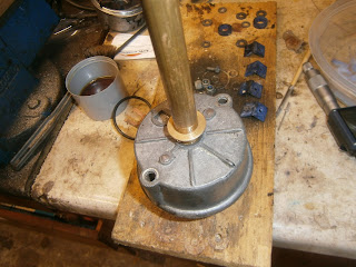
To strip further the next step is to remove the motor housing. The base of the spindle should be covered by a rubber cap and retained by a star washer- both were missing from this starter although I don't know if that's simply an earlier design. The large disc visible is the top of the "top-hat" oilite bushing (608352) in which the spindle runs. In my case this was cracked and the top just fell off when I touched it! Possibly this was because it had lacked the protective cover?
 |
| Top of top hat bushing central but... |
 |
| Not actually connected! |
The motor case is held to the bracket housing but long through screws. I found these were really tight and I needed an impact screwdriver to shift them.
The screws did eventually come loose but they are looking corroded. The base plate then pulls off with the brushes inside. These are sprung along the longitudinal axis of the motor and so are held against the flat commutator on the back of the motor armature. It was very dirty and dusty inside. The end cap and brush housing remains held to motor body by the brush wires which are soldered/bolted to the motor body but the brushes can be eased out and the wires carefully unjammed to separate the housing. This leaves 2 brushes soldered to the protruding copper strips in the motor housing and 2 soldered or fixed to the brush housing.

I found a loose washer on the shaft- not sure if this is original. The commutator seemed to be in good condition but needs a clean. The base plate didn't seem to fit onto the motor housing very well- seems a little distorted which might explain why the screws were so tight. It also seems that this join has let some moisture in over the years hence corrosion on the screws.
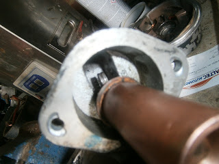
The motor armature is still held in the motor housing by the drive and bracket assembly at the other end. To remove this you need to take out the old and very worn square seal between the motor and bracket housings.
 |
| Seal between drive bracket and motor body removed. |
...and then the drive bracket housing could be removed. There should be a seal between these two housings but in my case it was also missing. Note pin (lower centre) that holds the lever arm in place inside the bracket housing and acts as the pivot.
The pin is fitted by pushing through the housing and bracket and then expanding its hollow end with a swage or drift. To remove, drill out the expanded free end of the pin and knock it back through with a punch.
Pin removed
This releases the pivot bracket inside the bracket housing. Withdraw armature from motor housing against the magnets ...
 |
| Armature out of motor housing- note discolouration to central cylinder- dirt, corrosion or arcing? |
... and then pull the top of the armature and drive section out of the bracket housing. I found that the armature was corroded and possibly burned through arcing. I cleaned it with v fine sandpaper and contact cleaner.
Drive section- spin gear and pivot lever that pre-engages the starter gear. Note the pin hole in the pivot arm- in my case this was elongated and distorted. Looked to have been replaced with something that didn't fit at some point. The pin I removed was also worn.
 |
| Pin heavily grooved from bracket |
 |
| Bracket pivot hole is distorted and worn |
I then tried to clean up everything making liberal use of contact cleaner spray and a nylon brush. I found in particular that the copper wires at the end of the armature were filled with carbon dust which brushed away leaving them nice and shiny!
End of solenoid needs a clean
Inside of motor housing also full of carbon dust- cleaned with contact cleaner and brush/wipe out
cleaned housing
Brush housing also cleaned out
Since the bushing had broken I was pretty sure I should try and change it. It was visible inside the cover and so I just tapped it out and then sought a replacement.
 |
| Looking through motor housing to brush housing and its bushing. It would have been easier to separate the two by untangling and removing the brushes (as above) but I hadnt thought of that yet! |
Knock out with a punch
bushing released
I was also concerned about the wear in the bracket hole and mounting pin. This will also need some attention so ideally I'd like to remove the drive unit from the end of the armature shaft. However, this is held on by a "stop collar" which is itself retained by a snap ring fitting into a groove on the shaft. The trouble is that the snap ring is recessed inside the collar and there is no provision for either expanding it or levering it out. I think this collar/ring assembly is impossible to remove without destroying it!
 |
| Stop collar on end of shaft |
Snap ring inside collar- no room to open this up and remove!
 |
| Close up of the problem. |
Strategy:
The bracket and drive assembly on my old starter unit was in much better condition than those on the starter above, the gears were less chipped and the pivot bracket wasn't (so) distorted. New pivot arms and larger parts are available from autoelectricalspares, but these parts are quite expensive. To avoid this cost I could simply swap the entire armature and drive assembly from the first motor into the housing of the second. However the field coils in that first motor were obviously burned out and possibly also those in the armature. I did try it but the motor wouldn't work. Consequently it seems that the best course of action would be to swap the drive section from the first motor onto the armature of the second, carrying the pivot arm with it. I may need to swap the bracket housing as well since this original motor seems to have used a narrower pin which might be too loose in the housing from the second motor where it seems the pin may have been bodged (sorry "replaced") with a thicker substitute. I will also investigate swapping the brush housing at the other end of the motor since this had also seemed distorted and out-of-round. Finally I will swap both oilite bushings (brush housing and bracket housing). I can try to reuse the seal between bracket and motor housings and use some instant gasket to try and replace the dust seals that are no longer available. At this point its clear that I will need some new parts at least: I need new
bushings, replacement seals and a new stop collar and snap ring. Parts for these motors are not readily available and can be very expensive. The bushes (Lucas part no 54245343) can sometimes be tracked down. I found that autoelectricalspares.co.uk stocks a pattern part at a very reasonable £1.60 and a stop collar 138683 that replaces Lucas TLB186. Seal kits are not available and I wasn't able to find a new pin at a reasonable cost. I ordered both parts.
The new parts were pattern manufacture- here are the bush kits and the stop collar assembly. The oilite bushes were put to soak in engine oil overnight before fitting. I was however now in a position to swap the drive assembly from the defunct motor onto the working armature in order to get the best unit.
What information Lucas does give is silent on the best way of removing and refitting the stop collar and snap ring. It was impossible to remove the old stop collar without destroying it- and even then it was difficult. I tried using side cutters but simply broke my favourite pair- a JCB set. It seems that this is a hardened metal. Similarly I couldn't saw it either as a hacksaw blade made little impression.
Eventually I removed the collar by clamping the collar (not the shaft) in a vice and cutting it with a cutting disc in two places so that a section could be removed. A Dremmel may be best for this although I used a full size disc taking care not to mark the shaft.
Eventually the snap ring could be eased out but this also needed to be weakened with the cutting disc before it would do so. However, it did come off eventually and the drive mechanism then rotated freely off the shaft.
... and slipped easily onto the other armature.
Fitting the collar was easy- it just slips on recess side uppermost, however it was very difficult to fit the new snap ring. Most attempts result in it pinging away across the workshop so cover it with a light cloth to contain any such rebounds!
 |
| New kit- collar and snap ring |
 |
| Collar slipped on |
Eventually I managed to fit the ring by compressing it with a pair of mole grips. You need to use plenty of padding to protect the shaft. Place the ring open side against the groove and compress it against the shaft ... In my case with Mole grips. This caused the ring to open and clip on.
 |
| Ring and collar in place. |
The next step is to swap the bushings- the instructions call for them to be fitted using a polished mandrel 0.013mm larger than the shaft. Presumably this is to prevent the bushing crushing and closing up so far that the shaft can't slip in. This deformation is usual, and would normally be addressed by reaming to fit the shaft after the bushes have been inserted. In this case the advice is not to ream as this can prevent the lubrication action of the bushes so the over-size protection is presumably the next best thing!
I measured the shaft to see what size mandrel would be needed. At this stage it was evident that the shaft has suffered some wear as it was wider at its tip than further down where it would pass though the bush.
It not therefore clear what size mandrel should actually be used. Given the wear I may just use the shaft itself (from the defunct armature) to allow the bearing to close up a little more and become slightly narrower.
I fitted the top hat bush by supporting the inside on a tall socket that jkust surrounds the bush hole.

I made a mandrel from brass in the lathe. I know this is a mandrel or mandrill- not sure which but one being a brightly coloured monkey. I tried that first but he was useless, didnt understand how to use a hammer and crapped on the garage floor!
I made a brass mandrel with a narrow section the same size as the motor shaft 11.94mm and checked that this slid smoothly inside the bush
 Tapping the bush home
Bush inserted
 At the other end I removed the bush by tapping in a socket of the correct diameter and finishing off with a flat ended drift.
 The new bush was inserted using the mandrel as above.

End bush inserted
 Once in I checked motor fit- there had been no appreciable closing up of the oilites and the motor shafts slipped in smoothly and easily.
 |
| Test fitting motor shaft into new bracket housing bush |
I could then start reassembly. I had inspected the brushes and found them all less than half worn. Given firstly that its difficult to solder/braze the new brush lead to the long copper contacts emerging from the motor housing, and (b) the fact that I had ordered the wrong brushes, I decided to refit the originals. The brushes were inserted into their sprung slots and the wires carefully poked out of the way before the armature was slipped in from the other end. Remember to include the bottom washer on the shaft (I forgot it and had to dismantle the motor to put that in!)
 Finally I was able to add the top bracket housing and secure the whole with the through screws.

I refitted the star washer and shaft cover boot before installing the solenoid.
The solenoid house was then bolted back on remembering to include the loose spring under the working cylinder and to fit the square seal under the solenoid house to cover the opening.
 |
| Seal Under solenoid housing top |
I couldn't find a clear picture of how the bracket lever connected to the solenoid and, because this was invisible inside the housing I hadn't noticed when it was stripped. However there is a tell-tale wear mark where the bracket lever penetrates the solenoid slot and is retained in place by the smaller spring. The pic below shows how it does fit, but its not stable until inside the bracket housing.
 |
| Lever and solenoid connection |
You can assemble it like this and then put the combined armature-solenoid cylinder assembly into the housings - or, as I had already installed the armature and joined the housings together with the long screws, its also possible to poke the spring-and-slot-plate into the bracket housing until it clips over the lever.
 |
| Inserting the cylinder (spring/slot plate first) into the bracket housing until it clips over the lever arm |
 |
| Close up of lever/articulation |
The bracket was secured with the undamaged pin and the ends spread with a punch to retain it.
 |
End of pin before swaging.
|
The solenoid casing can then be added (don@t forget the large diameter spring) and bolted onto the bracket housing.
 |
| Bolting the solenoid back on |
The two copper studs on the base of the solenoid accept the positive feed to turn the motor. However both were distorted- probably because at some point someone has used the incorrect nuts which have distorted the threads. This is to some extent understandable because Lucas in their wisdom used a 5/16 Whitworth thread on these studs; few of us have suitable nuts kicking about once the originals have been lost. It is possible to re-tap the studs but its tricky to get down to the very bottom because various molded lugs on the solenoid base obstruct the die. However, I was able to restore the 5/16 thread over most of the stud's length, and between the two motors I could summon up at least one correct nut- I still need another.
 |
| Restored 5/16 Whitworth threaded stud |
Next I re-attached the star washer to retain the armature shaft and finally covered the end bush with the rubber boot.
 |
| Star washer retains armature shaft |
 |
| Rubber boot |
Finally the motor was complete so I hooked it up to a battery. Activating the solenoid with a second lead started the motor running. Apparently the free running speed of this motor is around 200 rpm so I will test and report later*.
So good news! I now have a decent motor to store as a spare made from the best of the parts I had plus new bushes. I also have a pile of bits I can safely discard!
* Tested motor spin speed using eBay tachometer... Also good for lathes and drills... Guess what? 220 rpm free rotation speed! Great news.


Did you see a large adjustment nut on the starter that I assume adjust the Bendix pinion gear space to the flywheel's ring gear ? I ask, as my '66 Jaguar E-type was just rebuilt and worker could not find a new Bendix pinion gear; anyway now the starter motor itself spins great, but the Bendix fails to engage the FW teeth ! So the distance space is off, do you have any idea which direction that large screw adjustment would decrease the pinon to FW teeth ?
ReplyDeleteThanks
Hi, is your starter inertial or pre-engaed. Im not sure that adjustment is always possible but sometimes it can be. Try here... scroll down a bit but ghere is a section on setting clearances at least.
Deletehttps://www.howacarworks.com/ignition-system/replacing-the-bendix-gear
Hi, just though I would add a comment to this great account of stripping a 3M100 starter motor as I have used it to strip a similar 2M100.
ReplyDeleteThe snap ring and collar can be removed keeping them both intact by firstly driving the collar off the snap ring towards the coils. I used a socket over the end of the shaft. The snap ring can then be prised out of the groove, I used circlip pliers to open up the ring and get it out of the groove. The collar is then easily removed.
When re-fitting, firstly fit the collar onto the shaft, I then used a set of pliers to squeeze the snap ring into the groove as it had stretched a bit on removal and then used a puller to pull the collar over the snap ring. Note there is a taper in the collar to help feed snap ring into it and this taper should face towards the end of the shaft.
Hope this helps.
Hi - very useful post. I'm rebuilding a 2M100 at the moment but I'm having trouble finding out the size of the two snap rings so I can replace them. Are they something like M16 and M3? Thanks in advance :)
ReplyDeleteHi there, glad it's helpful! Sadly I didn't measure the snap rings but my guess is that they're not expensive so maybe get a selection? Simply bearings do them, although these items on ebay have a min order of only 2
ReplyDeleteLook at item 293732013102
Thanks Mike, Thanks for coming back to me - soz I meant the two star rings, or officially the "spire nuts". I destroyed mine taking them off and the Hayes book says to replace them anyway. Thanks!
ReplyDeleteHi again, I didn't measure starlock washers either, but if you google them you can find the range of shaft sizes they fit, there's a good deal of leeway.
ReplyDeleteI've got a selection from ebay and just use them as needed. They always come in handy, just fixed my lawnmower with them!!!
Thanks Mike will look into it
ReplyDeleteHi Mike,
ReplyDeleteAlthough from a few years ago this is still an excellent description of your motor rebuild. I have just done a similar job on a Lucas 3M100 fitted to a 1988 anchor windlass on a sailboat. You mentioned that you had bought the wrong brushes. I had a similar problem. When I went to fit my new 3M100 brushes they were the same shape as the old ones but slightly smaller. I ordered another set from a different supplier, and same problem. Did you ever find the right new brushes for your unit? I'm wondering if there was more than one size for the brushes but I've been unable to find any info online.
Thanks very much for your help.
Cheers, Simon