Refitting the Flywheel
The flywheel is held on to the mating flange on the crank by 6 bolts and 2 dowels. The wheel can in theory fit onto the flange in one of two orientations 180 degrees apart. However in only one of these orientations does it sit concentrically and do the holes line up.
 |
| Flywheel in incorrect location- centre boss does not sit concentrically inside flywheel- tighter at bottom right than top left. |
 |
| Flywheel fitted 180 degrees from first position- gap is radially symmetrical and bolt holes align. |
 |
| Bolted on. |
Once in the correct alignment the bolts were refitted and torqued to 50 lbft. The flywheel would only mount concentrically in one of its two possible orientations. In this position the holes lined up as well.
I fitted the original clutch from my car, this should obviously fit the gearbox! I used a Draper universal clutch alignment tool- Its really quick and simple but having seen how it works I think cheaper equivalents would be just as successful... Fit a sliding tapered spacer (taper towards screw thread end) that fits into the clutch friction plate splines and a smaller screw-on spacer that fits the spigot bearing.
 |
| Assembled tool- spigot insert screwed on the end and the tapered adaptor fitted on the shaft |
 |
| Tool in use. |
... or at least I could have but I found it very hard to reuse the screw from the previous fit. Looking at these, they are cut down bolts... also they are M8 threads and have clearly distorted where they have been tightened! No way round it, these are the wrong screws! The LBPO strikes again! I had to order some new 5/16 UNC 3/4 bolts which thankfully fitted easily. Luckily the bolts the LBPO had used were softer than the flywheel steel and the flywheel wasnt damaged.
 |
| Old bolt- wrong thread and wrong length! |
 |
| Pressure plate fitted. |
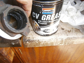
Opinions seem to differ over whether to grease the clutch mechanism. The hub is recommended for a smear of Lithium based, Molybdenum disulphide non-fling grease and cv grease seems to fit this description.
I also applied a light smear to the face of the thrust washer before fitting the CRB back onto the arm. I noticed that the past clutch had been fitted using copper anti-seize grease- this isn't non-fling so I wiped most of it off. There seems to be enough remaining so I didn't use any additional grease on the splines.
The Clutch release bearing clips onto the actuating arm via the "wings" on the hub section. The parts manual shows the clips fitted with their open ends towards the motor- as below.
 |
| CRB clips fitted as shown in parts manual-open sides forward |
 |
| Clips fitted "closed" side towards motor, hub projections slip into the closed part of the clips. |
This does seem a better configuration- although I am now assured by the forum that its wrong. However, I found the CRB installed this way and as the alternative does seem a bit loose, I'm going to stick with it.

No comments:
Post a Comment
Feel free to let me know what you think of this blog. I'm working on my own here so any feedback from those Lotus enthusiasts floating around "Blogger Bank" is welcome. Suggestions for process improvements especially welcome. If you like it please follow.