Fitting Water pump and power steering bracket
I removed the power steering bracket from the old motor- cleaned and repainted it before fitting it to the two extra long sump studs on the new motor. I was having to work out which bolts doubled up with both water pump and steering pump bracket or other ancillaries.
I found I lacked all of the 4x 2.5 cm M6 bolts that hold the water pump although I did have the longer 6.5 cm bolt through the centre; strangely in my case this turned out to be a 7.0 cm bolt fitted with a few extra washers! I will reduce it in length before I fit the pump permanently.
I did however confirm that the water pump and head can be fitted independently by making sure that the two didn't interfere. The manual tells me that some motors must have the water pump removed before the head can be installed or removed so it was best to check. This process also reminded me that the pump slips down behind the steering pump bracket so I will need to make sure I have the right bolts. I ordered new bolts and washers as needed and left the pump loosely installed while I proceeded to the next step.
Exhaust Manifold
It is virtually (completely?) impossible to access all the exhaust manifold nuts when the head is on the motor, so I refitted the exhaust manifold before fitting the head
 |
| New Brass M8 nuts, and copper M8 16mm washers- these are the deeper head nuts 0.5cm |
 |
| New gaskets. Studs smeared with copper grease to try and prevent siezure in use. |
I used deeper brass nuts so that there would be a larger surface to grip when undoing them, new M8 16 mm washers also used. Tightened to specified torque. Note that these nuts cannot all be accessed together and its necessary to fit the lower nuts as the manifold is pushed onto the studs . If it is pushed home first then there is insufficient space to get the nuts onto the studs.
Refitting the head
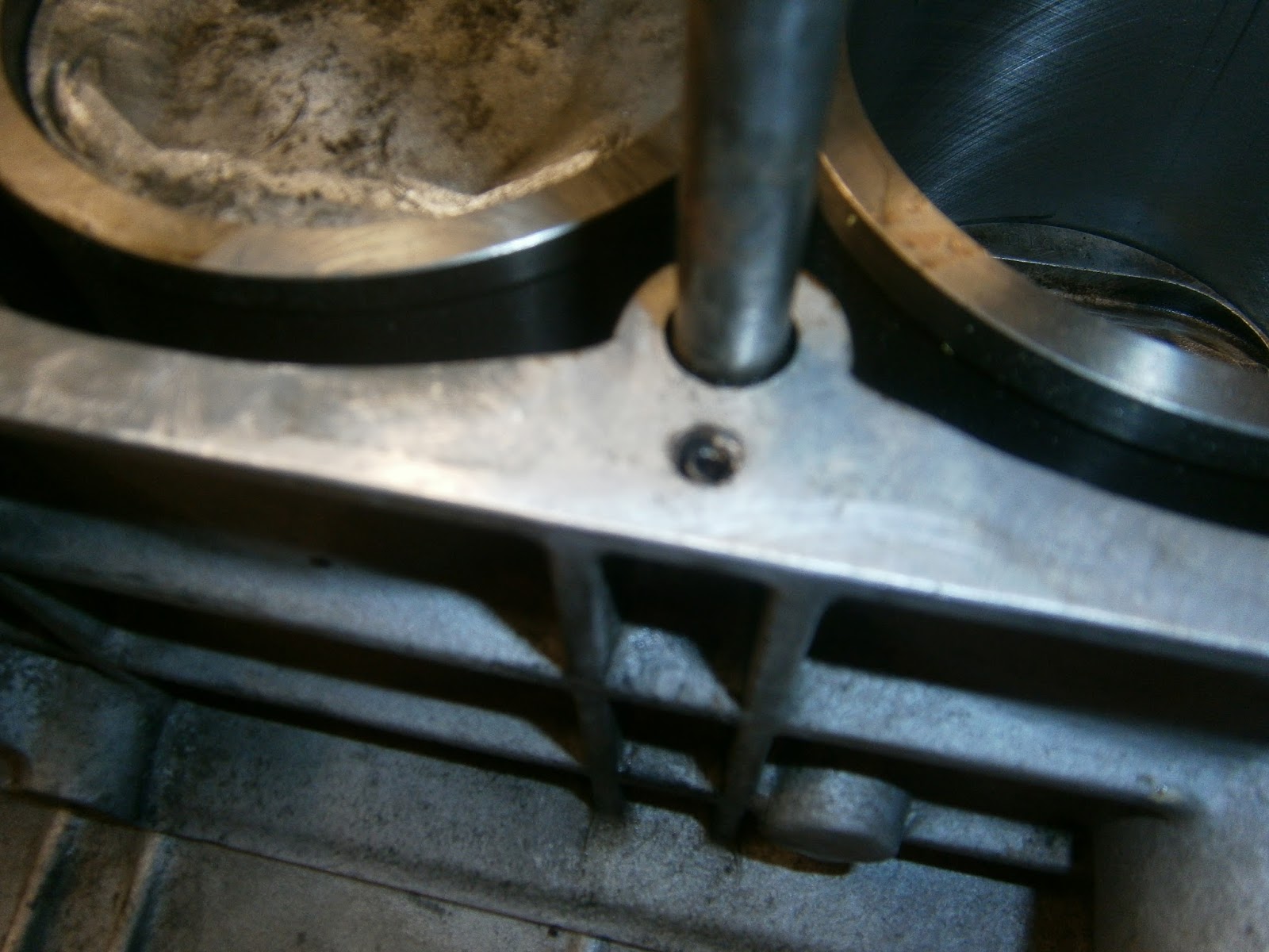
I did notice that one of the 2 spiral roll pins in the block existed as only a stump. This was either the remnants of a degraded pin or perhaps a replacement thinner pin installed inside the remnants of the old which persisted in the socket once the stump was removed. Sadly these pics aren't focussed very well....
 |
| Remains of roll pin after stump removed. |
 |
| New pin- not a simple roll-pin but thicker and spirally wound |
 |
| and installed. |
 |
| Motor 90 deg BTDC |
 |
| This brings all the pistons to app. half way and out of the way of any protruding valves in the head. |
I turned the bottom half of the motor to the timing position and then 90 deg backwards, bringing all the pistons half way down the bores to avoid valve damage as the head was fitted. I "dry-fitted" the head a few times using the old head gasket to check that it would fit easily whilst making sure I didn't damage the mating surfaces. The new roll pin did need some adjustment before the head would slip on smoothly. It was at this point that I noticed my mistake and was forced to remove the cam carriers so that I could access the head bolts (ooops!). However, although it was a little fiddly, since the tappets were already sorted it didn't take very long.
Cam carriers then reinstalled. sealed again with PG307 as before. Note water pump and tensioner are at present only loosely held as I wanted to be sure I could fit them after the head and I wanted to make sure that I knew where to put the various spacers and brackets. The tensioner as fitted is my old one from the second motor and doesnt have any internal parts. I will need to fit properly the pump, power steering bracket and crankshaft pullies before I can put the camshaft pulleys into the timing position, make sure the distributor is in the correct orientation and turn the motor forward to TDC before I can fit the belt and the rebuilt tensioner.
The Tensioner
This had been the first part I removed from this motor and its satisfying at last to reassemble. However it will be easier to assemble the tensioner if the pulley is fitted after the spring is installed. I had bought new springs, plunger and spacers for the tensioner, but even so I found that the piston was a very tight fit in the barrel portion of the tensioner- it was in fact impossible to push it in far enough to reach the locking position (groove aligned with pin hole) and if it was forced, then it simply stuck in the channel- which of course means it couldn't tension anything so I enlarged the casting hole carefully with Emery paper until I got a tight but sliding fit.
Assembling the unit using a vice to compress the spring
I have bought a renovation kit with new piston and springs as well as the locking pin- a word of warning I did try a few ordinary pins but they didn't hold the tension and I was forced to spend a good 10 mins grubbing around the garage looking for the piston and spring after such a failure! Be warned- use the right pin!
 |
| Unit assembled ready for the bearing |
Water Pump
The new bolts arrived and I spent some time dry- fitting the pump and tensioner to get the spacers right.
The motor has been tilte so that the camhousings are more upright in this picture- and this has tilted the pump downwards but here the pump and tensioner do fit well. The pump slips in behind the black bracket for the power steering pump on the right. I removed this bracket before fitting the pump so that I had a clear run at the mounting point.
The tensioner is fitted in place in this pic, but I couldn't attach the centre stud nut as the piston retention pin fits under the spacer and washer for this nut. I have a quandry here since the two motors that I am dealing with had different approaches to alternator belt tensioning:
The motor in the car had a straight canted adjustment bracket attached on the centre stud of the tensioner; the motor I bought as a second, had a curved and canted alternator adjustment bracket attached at the upper tensioner hole by a bolt. This hole was vacant in the first motor. I cannot tell which arrangement would give the best fit until I attach the alternator so for the time being I will use the second approach.
 Motor in the car: Alternator adjustment bracket fitted to tensioner centre stud, top bolt hole vacant
 |
| Second motor, curved alternator adjusting bracket fixed to tensioner top nut. |
 |
| Tensioner in place, bracket on top bolt, centre stud left free as pin still in place. |
I assembled the tensioner by bolting the bearing into the forks and fitted the unit to the motor leaving the pin in. I couldn't fit the nut washer and spacer on the centre stud at this stage owing to the tensioner locking pin.
 |
| Treat pump face with Wellseal |
 |
| Apply gasket and treat that with Wellseal |
I then offered the pump gasket assembly to the block and secured with the long (70mm) centre nut and 4 peripheral M6 Nuts. Those which had to penetrate both the paum and the power steering bracket were really a little too short and although I have fitted them I have also ordered some additional 30 mm M6 bolts for this position. One of the fastenings is recessed behind the aux housing pulley. I do recall deciding to swap this nut for an Allen cap bolt which can be accessed beside the pulley since there is little room to turn the bolt, let alone getting a spanner onto it in the first place. Sadly I had forgotten to get an Allen screw, so I pressed on with the bolt. In fact it was just possible to fit it by hand since without the belt the pulley was free to turn and assist in tightening the bolt until its head was below the pulley. I wouldn't like to try this with the belt in place. I found a small and offset spanner helped with access here.
 |
| Inaccessible bolt shielded by Aux pulley |
 |
| Offset spanner gives some access for tightening. |
The next question concerns the timing of the motor. The head/camshaft and Aux housing come from a motor that had a catastrophic cambelt slip. I couldn't therefore be sure that the alignments I found on them are correct. In particular I need to make sure that I am aligning the pulleys using the correct timing marks.
 |
| Cams- 777 marking |
 |
| Engine No commences DT912 |
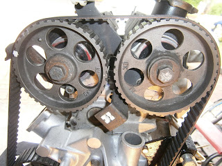
The manual explains how different versions of the 90-7/912 motor used camshafts with different valve opening characteristics, termed maximum open position (MOP). The engine number shows that the motor came from an Elite/Eclat/Excel automatic- according to the manual this means its a type 9 setup. The head and camshaft come from a later motor (84 Excel) but have cams with the 777 marking. This is most likely also a type 9 motor, but its just possible it could be a type 10... however, both types 9 and 10 are timed using the green timing spot on the camshaft pullies.
Herein lies the problem, not all my pullies have green spots. Currently the exhaust pulley has its dimple facing to the rear and a single green dot in the same place on both front and back sides. The side facing forward has the green dot next to the "EX" marking. The inlet pulley has the dimple facing forwards and carries two dots on the front face. Both are however white- and this doesn't feature in the manual at all. One is present on both sides of the pulley (looks like it was always white on both sides) and on the forward-facing side it aligns with the "IN" marking. The second dot is only on the dimpled, forward-facing side and it has been painted white. On both pullies there are 15 teeth between the dimple and the dot present on two sides although for the inlet this is counted clockwise and for the exhaust its anticlock.
Finally there is the pulley on the aux shaft. This I know is as it was when I got the car as I haven't removed it. It carries two green dots on opposite sides and a third white-painted dot on one face only. Currently this is the front-facing side with the dimple outwards.
Strangely all three pulleys have the same part number in the parts list so I am confused by the apparent differences in the dots they carry.
However my problem is which marks do I use to time the motor? My best guess is to use the IN and EX dots on the two camshafts and the third white-painted dot on the distributor. However it seems likely that at some stage the Aux pulley has been swapped for a camshaft pulley - its pattern of green dots is too reminiscent of a camshaft pulley and one of my camshaft pullies has white not green dots.
 |
| Camshaft pulleys, note white and green dots. |
 |
| Marks are almost in alignment |
The dots do not align exactly, but to some extent this may be due to the initial fitting of the belt. At this stage tension doesn't seem to be evenly spread and either pulley can be moved slightly without actually moving the others and this shifts the dots into better or worse alignment. I think the situation will become clearer once the motor has been turned over a few times to spread the tension. I will re-examine the dot positioning then. However it would be daft to turn the motor over until the belt is tensioned as resistance to turning will cause the teeth to slip. I will tension the belt once I hear from the forum members that its OK to proceed with my pulleys in this way..
 |
| Oil pump pulley alignment. The third spot (painted white) is aligned on the midline between crank and oil pump pulleys. |
Well everyone agrees that Lotus never used a white timing dot. This means my pulley is probably a repainting, but if so then the original colour has been lost. Owing to the history of this head I really need to be sure.
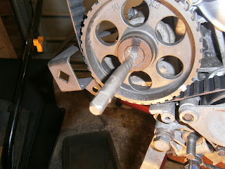
Of course the pulley on the oil pump is green spotted so I decided to swap this for that on the inlet camshaft... However, easier said than done! The hex socket on the aux shaft pulley was rusty- and the first thing that happened was that the hex socket stripped! This pulley simply wouldn't budge. I recalled that this pulley is supposed to be loctited on and so treated it with localised heat using the creme brulee torch (Silverline butane). I could still get no purchase on the hext socket so I drilled another small hole for purchase and tried to tap the screw round with a punch. The pics show what happened.
 |
| Hole drilled for purchase |
 |
| Punch to try an tap pulley round |
This still failed to budge so in despreation I drilled a short hole and used a stud extractor. I have used these before- and pretty much always without success. In many cases they simply break off in the hole and the hardened stump then makes the situation even worse. However, I was running out of options so I tried it... and to my amazement it worked perfectly. I suspect the heat and tapping had loosened the screw sufficiently that the extractor's grip was sufficient. Of course this is the first time I have used my set of Dormer stud extractors and maybe its a sign that these are much better quality.
 |
| Stud extractor inserted, turn anticlockwise to grip and unscrew. |
 |
| Screw removed- it is certainly clagged in with some sort of sealant |
 |
| Screw and special washer removed- the shaft and pulley look pretty rusty |
I had to use an extractor to remove the pulley, in my case a 2-jaw tool from my blind bearing removal set. I reinserted the damaged screw to protect the end of the shaft before tightening the extractor against it. It took a lot of force, but it did come off in the end.
 |
| Shaft is quite corroded- cleaned with nyloscour pad. |
I had a very helpful reply from Tim Engel on lotus4seaters who suggested that whilst the pulleys were off, they could be compared by aligning their timing dots and teeth if the same side (I used IN) was uppermost. If the pulleys are the same then the keyways would then also align- if they were for different degree MOPs then there would be a misalignment. I carefully aligned them and their keyways coincided- which suggests that in fact the pulleys were identical. It also means that I didn't need to swap the pulleys but given the history of this motor I really couldnt proceed without reassurance.
 |
| Pulleys aligned- keys in same position. |
I replaced the pulley; Lotus recommends that this pulley should be fixed with Loctite. However I couldn't bring myself to do this as it makes disassembly so difficult. I suspect that there may well be trouble with the aux housing in due course because this was taken directly from the car. I am expecting therefore to revisit this pulley and Loctite at this stage could be premature.
I realigned the motor to the timing position and fitted the timing belt. Its important to slacken the tensioner mountings so there is enough play in the belt to slip it over the pulleys. Obviously you dont want the motor to move while you do this. If the motor was in the car then I could put it in gear but as its out I fitted the belt in the order engine tensioner ex pulley and inlet pulley last to give it some resistance. I got this general guide from the forum...
The pin locks the spring plunger in the most closed position, you can only install with the pin in place. Slacken slightly the tensioner mounting nuts to allow the pulley a bit of sideways slack (this is not the spring adjuster nut, and on some tensioners the locking pin normally means the mounting washer and nut are not in place).
Fit cambelt to crank pulley, exhaust then inlet sprockets, tensioner pulley, and then by tightening the belt using a spanner on the inlet sprocket securing bolt (anticlockwise) you will get enough clearance to slip the belt over the auxiliary sprocket. There is sufficient adjustment on the distributor to later correct timing if you are a sprocket tooth or so out of line on the auxiliary sprocket.
Start tightening the spring adjuster screw until the pin is freed, install mounting washer and nut and tighten, then adjust spring adjuster to get correct belt tightness.
I could then tension it by removing the tensioner locking pin. Once this was out I could refit the nut washer and spacer to the centre stud and tighten up all the tensioner nuts and bolts. I then tensioned the belt by screwing in the adjustment screw.
 |
| Removing the tensioner pin- bit of an anticlimax, I had expected a satisfying click but nothing obvious happened- although the belt did get a little tighter. |
 |
| Tensioner nuts and bolts replaced. Note that I have re-installed the earthing strap that was missing from both motors. |
I checked the timing was still OK and then tensioned the belt to app. 110 lbs using my Cummins Burroughs gauge. This is really intended for thinner belts and using the thick square toothed Gates belt meant that the zero position deflects by a couple of mm even if there is no tension on the belt at all. This is a distance deflection, not a pressure deflection and I'm treating it as a constant 2mm alteration of the reading even though the scale isn't linear. It has more effect as the tension increases but. I calibrated the tensioner busing the old belt. I cut this and pop rivetted each end into loop.
I could then hang this up and hang weights from the lower loop in order to measure tension the single region. The two front wheels and my toolbox came to 88lbs. At this weight the gauge read app 20 lbs over at 105lb.
I was then able to turn the motor over by hand. This was smooth with a few tight spots which I think are due to valve spring compressions. There were no nasty clunks or stops so I was able to turn the motor over app 4 times before rechecking the timing settings and tension- all were still spot on so I'm a dead happy bunny!
 |
| Alignment of green dots after turning the motor and setting the crank back to TDC. |
 |
| Alignment of distributor timing dot (painted white)on the centre-line between aux pulley and crank |
Having set the belt using the calibrated Burroughs Cummins I was able to see what reading I would get on the Draper tension gauge.
 |
| Draper belt tension gauge |
This one works in a different way and requires data for belt deflection force and magnitude that neither Lotus not Gates supply. However, now I know that the belt is correctly tensioned, I could use the Draper gauge and I can say that the correct tension corresponds to a reading of 17 on the Draper gauge. To show this set the gauge on 15 using the main scale. and apply to the belt. The second pointer is then deflected two divisions down at 13 on the scale. Winding up the main roller shows that both scalecoincides at 17. This should be fine for all Gates square toothed belts but might differ for other makes or tooth patterns- although I suspect it will be about right.
 |
| Main scale set on 15, secondary scale marker deflects an additional 2 markings on the scale and settles at 13. There is a flare in this picture but the secondary scale marking ids the white line to the left of the reflection. |
Overall a successful conclusion to a troubling episode. I am happy that the belt is tensioned correctly and the timing is right.


Great restoration log! Very detailed and informative. I enjoyed reading it, since I'm restoring 88' Lotus Esprit Turbo. Perhaps you can help me?
ReplyDeleteI'm trying to retrofit a hydraulic power steering into my car. Lotus introduced P/S on 93" and later models. Saginaw APS pump bracket, which they used, does not fit my (early) block. I was advised to use Excel pump and bracket. I have the bracket, which conforms to this block and 3 attachment points. Recently, I bought Hobourn-Eaton FNF4-2-59 Original Pump, but have no idea how to attach it to the bracket. There must be an intermediate mounting plate, which I'm missing. I have no idea where to find one nor how it looks. Would you please snap a picture of your arrangement?
I would greatly appreciate any help in this matter.
Cheers
John