Well Dear Reader, its now 3 months since my front bumper was damaged by the garage... Still not repaired. The garage initially offered to have the GRP filled and resprayed. However, although I don't understand the difference, Miles Willkin at Fibreglass Services (who knows a thing or two about Lotus bodies) says that this is a "rubber" bumper which cannot be repaired in anything other than a cosmetic sense.
I was puzzled by this reference to "rubber" because the bumper looks just like GFRP to the untrained eye (ie mine). The Lotus parts list does give two different bumper compositions RRIM and GFRP. Prior to 1985 Excels were fitted with a one-piece integral spoiler-plus-bumper made by RRIM. This process, (Reinforced Reaction Injection Moulding) consists of two or more resin components mixed under pressure in the mould. However, the acronym also stands for "Rubber Research Institute Malaya" and I think this might account for the belief that rubber was somehow involved in the structure of the bumper- but I'm not convinced that it ever was. After 1985 bumpers were made in either GFRP and RRIM and were made in at least two new designs (a new integral version and a newer version with separate spoiler). If all this is correct then I think it means that my car (1984) should have the very first integral bumper design made from RRIM, and its this material which cannot be repaired with GFRP procedures. RRIM bumpers need to be replaced entirely.
Well the early RRIM bumper is of course no longer available but a GFRP copy is listed on the SJS website and made to order. Lead time app. 7 weeks. Miles estimated about £1k to fit it, but I suspect this was because he didn't want a dirty and time-consuming job just as he was about to retire and close the garage! The bumper bolts are pretty much renowned as pigs to undo owing of years if spray-induced corrosion! Anyway, I have ordered one of these and will fit it myself as I want to know what's been done. Its likely to be time-consuming and awkward- but in essence, its only a bolt-on job and doesn't require fibreglassing or bodywork expertise. I will however ask the garage to spray it.
After 7 weeks the new bumper has arrived, so I set about removing the old bumper.
Removing the front bumper
This early front bumper isn't actually illustrated in the parts manual, but its held on by a pop rivet in each front wheel arch, 3 screws ahead of each front wheel and accessible inside each headlight pod, a large central bolt behind the number plate and a self-tapping screw behind each front light fitting. The front light fittings themselves are installed after the bumper has been fitted and their mountings also penetrate through the bumper and have to be removed before the bumper will come away. My plan involves removing the light fittings, the three screws both sides and the front bolt. I can then remove the pop rivet and finally the screws screw beneath the light units to detach the bumper completely.
First step is to remove the headlight unit...

.. and then the pod.
Reaching inside the pod, uncouple the actuating rod from the motor lever- in my case this meant removing a single nut on the motor lever and the actuating rod can then slip sideways and off the motor. Do not unscrew the length adjusters on the actuating rod or you will alter the rise and fall distances of the lights when refitted. Apologies for the picture which failed to show anything at all!
 |
| Looking down into the pod- the cross brace is visible centre and the springs of the actuating rod are just seen, the rod itself is hidden by the cross brace. The motor is visible at the bottom above the access plug hole, the plug having been removed. |
Next remove the two pivot bolts at the back at the top of the pod. They don't need to come out entirely, just enough to unscrew them from the body and release the pod.

The pod can then be lifted away
 |
| Pod removed, note actuating rod with spring still attached at the top |
Looking inside the pod (here the RHS pod seen from the front of the car) the three screw fittings are seen running forward of the wheel. These also serve to hold the cable ties that retain the side light and indicator power feeds.
This is a point where I despair of Lotus- this location is guaranteed to corrode over time, yet Lotus used neither stainless steel screws nor even corrosion block grease. The screws themselves are simple cross-head, not hex head or Allen cap so its not possible to put any force on them, the heads just strip out! None of the 6 screws in my car would undo so I was forced to drill their heads off. Luckily the metal is soft and they come out fairly easily. They have a large flat washer beneath and a cable clip where appropriate.
Incidentally, these fastenings aren't shown in the parts manual which shows only the self-tapping screws used for the later style of bumper. The fittings in my car are machine screws fitted into immobilised fastenings in the bumper and I will replace with similar using aluminium rivnuts.
 |
| Heads drilled off side retaining screws. |
Looking towards the front of the lightpod cavity you can see the back of the moulding in which the sidelight/indicator light unit is mounted.
 |
| Sidelight mounting seen from inside the pod cavity. Unit mounting nuts left and right are earthed via wire straps. The power wires (green and red) enter through a central hole and the tip of the self tapper behind the light unit is just visible between the central wire hole and the RHS mounting nut. |

I removed the two nuts (these are tapered to fit through the GRP and tighten onto the light unit itself). One of these bolts sheared off and will need to be replaced.
The two power wires disconnect at the bullet junction tube. As usual some of these will pull the bullet off the wire rather than the bullet out of the junction tube! I repaired the bullets as needed and used dielectric grease to stop them sticking again.

The light unit then just pulls away from the front of the bumper.

Once the sidelights were out, the heads of the self-tapping screws behind are accessible. I left these in place to support the bumper whilst I removed the central bolt. To do this I removed the number plate; mine was held on with some nasty self-tapping screws which had rusted badly, rather than the usual plastic screws and nuts. I suspect that the design of the bumper doesn't really let you use the usual mounting screws. This revealed the central bolt which unscrewed easily using a socket on an extension. However I think this could be a real problem if the captive nut were ever to slip!
 |
| Central mounting bolt behind number plate and visible when the plate is removed. |
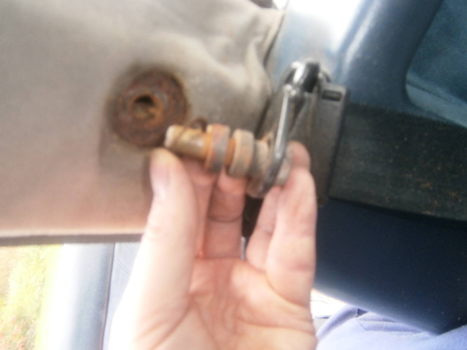
The only thing holding the bumper on now were the pop-rivets in the wheel arches and the self tapping screws in the light unit moulding recess.
 |
Finger illustrates the head of the pop rivet that secures the rear return of the bumper to the inside of the wheel arch.
|
I removed the pop-rivet heads by Dremmeling them out with a burr- using a drill would have meant raising the car and removing the road wheels.

Finally I removed the self tapping screws in the light unit recesses whilst supporting the bumper...
 |
Self-tapping screw behind light fitting (one each side)- it unscrewed easily enough.
|
... which could then be lowered away.
Leaving the front of the car like this- the air intake for radiator cooling clearly visible.
Once the bumper was off I could see the side mounting screws more clearly. They were badly corroded. The new bumper doesn't have these captive nuts so I will need to improvise with nutserts or rubber compression fittings.
I will need to remove, treat and respray this wire mesh intake cover as its starting to corrode. It will need to be fitted to the new bumper.
Note added later?.. On closer inspection and comparing my old to my new Grfp copy the RRIM material is altogether finer. Its denser and more homogenous and the fibre matting structure is absent on the back.
I removed the two wire meshes covering the 4 air vent openings and resprayed these after treating with Jenolite to stabilise any rust.
Other bits
Its important to take any remedial action whilst you have access, so I used the opportunity to clean and grease all contacts inside the sidelight/flasher unit and replace the sidelight bulbs for LEDs (checking for correct orientation). I didn't swap the indicator bulbs as LEDs will not work unmodified unless the flasher unit is also changed. Instead I just cleaned up the contacts inside the bulb holders and refitted the bulbs using dielectric grease.
One of the unit mounting studs had sheared so I replaced this with an Allen cap screw retained with a star washer. I was careful to preserve electrical contact with the bulb earthing plate.
One of the headlight bowls had started to corrode around the "sidelight" hole which is not used in the Excel. This is instead sealed with two rubber plugs visible to the side. I cleaned up and loose rust and treated the exterior of the bowl with rust converter. Finally I refitted the two plugs using silicone to try and prevent water access in future.
 |
| Treating the corroded area with rust converter., sealing plugs to right |
 |
| Refitting the sealing plugs using silicone. |
Refitting
What follows is a blow by blow account of what I did to refit the bumper- it wont make pleasant reading ! For what its worth, and for those who might be reading this because they are about to attempt this themselves here is my advice:
1. Fit bumper and drill all mounting holes before the bumper is painted.
2. Only drill sidelight unit holes and self tapper holes from the inside of the light pod outwards- and
only when the bumper sits properly in position.
3. You will almost certainly have to extend the central bolt hole downwards to allow the bumper to sit high enough.
4. Trim the air duct so that there is room for it to fit behind the bumper without holding it off the body of the car.
5. Check that the wire mesh grill conforms closely to the openings in the bumper base.
6. Use M4 rivnuts or self tappers to hold the sides of the bumper (not as I did M6)
7. Be prepared for the new bumper not to match exactly your old.
It took me three attempts to get the bumper to fit in an acceptable manner. Luckily with renovated threads you can strip and refit the bumper in an hour so its not as bad as it seems.
Well the bumper was 5 weeks in paint! The sprayer reported that he's had problems with paint adhesion which he attributed to moisture inside the structure- presumably either through contamination of resin/matting or in manufacture. This was a new bumper manufactured to order and supplied through SJSportscars of Devon. To be frank I wasn't that pleased with it as it tended to crack internally along the lines of the matting revealing what look pretty much like dry fibres to me. However, it is probably the only bumper for this type of car available and the paint did eventually stick (albeit a little like a powder coat and tends to flake if damaged). I clearly made a tactical error here in not drilling the bumper before painting.
However the bumper as received back from paint looked really good.
I refitted the air intake grills first, placing the grills in position and marking the points for the screws with an initial drill mark.
Before drilling through using a wooden block to help prevent breakthrough chipping- this worked quite well as far as the GRP was concerned but the paint did chip a little.
I sprayed all the screws Lotus A35 silver.
Only the upper screws can be reached easily from outside the car, so I screwed the lower screws in firsat passing the screwdriver between the upper edge of the mesh and the bumper. The upper screws could then be screwed in from outside.
Grills reinstalled.
I also fitted the number plate- I'm incorporating a plastic surround frame for effect here and so I drilled the bumper to accept the frame which I will fit when the bumper is finally fitted. However before I can actually fit it, I need to mark the positions for the rivnuts. I test fitted the bumper. This is really a 2-person job but I managed (just) and retained the bumper temporarily with the front bolt.
 |
| Test fitting the new bumper, use plenty of padding under the car as you will drop it if working alone. |
Looking inside the car the top of the bumper is visible through the screw holes
 |
| Fixing holes inside RHS headlamp pod. |
Which I marked with pen through the holes and
 |
| Holes marked for drilling |
Whilst the bumper is fitted use the existing body holes to drill through for the two indicator/sidelight unit mounting bolts, the self tapping screw hole and the cable exit... in my case this was a little premature.
 |
| Using the existing body holes to drill through for the light unit holes (3) and self tapping screw (1) each side. |
I removed the bumper and drilled the holes (8mm) for the M6 aluminum rivnuts. Aluminium rivnuts or nutserts are softer and can be installed without cracking the GRP. They will also not rust! However they are best installed using a washer (M8 drilled out to 9mm) to protect the body on the underside.
 |
| Rivnuts installed on one side. The centre nut shows the chipping which can take place along the matting as I mentioned above. This happened when drilling. White and apparently dry matting was exposed and is still just visible below the rivnut. This could weaken the GRP so an M10 washer was fitted beneath the bumper to contain the sideways forces as the rivnut was expanded. The edge of the washer is just visible underneath the bumper lip above, and will need to be filed back before the bumper is fitted so the side sections can fit flush to the body. |
To install the number plate frame, I used 4 plastic bolts, 1 in each corner, and added sticky pads to mount the number plate itself within the frame. I drilled a large central hole so that I could insert the centre bolt and its washer and also reach them with an extension rod in order to tighten up.
I cut the plastic bolts off short so that they will not get in the way of fitting the bumper.
I filled all the rivnuts and central bolt hole with copper grease to keep everything loose and then refitted the bumper; again it was very tight but I could insert the Allen cap screws and washers to hold the sides of the bumper...
... and then take them out again and refit them remembering to include the cable clips!
Finally I could install the number plate itself and refit the headlights.
Here is the new bumper installed

 |
| new bumper- seems slightly more forward than the original and has wider gaps. |
... and compared with the old.
 |
| Original |
 |
| LHS gap quite wide |
It seems quite clear that the new bumper hasn't gone back quite correctly and I have wider gaps than before: In particular it seems that it needs to move backwards slightly which would take up most of the gapping. I used an endoscope to see where the bumper has any contacts that are stopping it from going back correctly. This showed firstly that there is plenty of room behind the bumper for the plastic bolts that I used to secure the number plate frame. In fact I probably didn't need to cut them off.
 |
| Rear of no plate securing plastic bolts |
Secondly, the side screws threaded into the nutserts were not too long and were not fouling the bumper.
 |
| Side screws penetrating nutserts, the blob of copper grease has been displaced downwards but the end of the screw is clearly visible and isn't contacting the bumper. Damage to GRP was I think incurred in drilling breakthrough. |
So far so good. The nutserts themselves give a clue as to what may be wrong. Looking at the side gaps both show the same story. The nutsert tops act as natural spacers that set the panel gap between car body and bumper. The rear two on both sides are tight up against the body and the gaps are even. However, on both sides the front screw/nutsert is gapped. In fact on both sides its beginning to pull out! This has to indicate that the front of the bumper is too low.
 |
| Panel gap body to bumper lhs, front rivnut pulling out and has a wider gap at the front than the rear. |
 |
| Front of panel gap lhs closeup. Front rivnut pulling out, gap wider at front. |
Examination of the old bumper also showed that the central bolt hole- by default in the centre of the conical rearwards projection, has been extended downwards. This would have the effect of allowing the bumper to be installed higher; again suggesting that my installation is too low at the front.
 |
| Old bumper; central hole re-positioned downwards allowing it to be fitted higher on the car |
The endoscope also showed that the conical projection to the rear of the bumper doesn't quite meet the corresponding pad on the front of the car- the bumper looks to be too far forward.
 |
| Rear of bumper left. Conical rearwards projection visible- makes poor contact with the pad on the car body |
Similarly the bolts securing the sidelights no longer penetrate inside the headlamp pods as far as they did with the old bumper; again suggesting the bumper needs to go backwards a little.
There isn't really anything that could obstruct backwards movement at the front of the bumper. The the only contact at the front would seem to be between the top and bottom of the air intake box and the grilled opening moldings at the base of the bumper. I can't see these contacts even with the endoscope. It seems that around 0.5 cms in each direction would probably solve these problems and I will try to rectify both by extending the central bolt mounting hole and checking the fit of the air box against the grill mesh and its fixing screws. I may need to make some "scallops" in the front of the air box to accommodate the grill fixing screws so that the bumper can move rearwards a little.
So nothing for it then... time to remove and refit. Removal was very straightforward. I also removed the lower element of the air intake box
 |
| Lower intake duct panel removed as well as the bumper |
Having done this I could see scratches where both upper and lower parts had been scratching or jamming on the screws securing the intake grill. Using these marks as tell-tales I used a rotary file to score out scallops to accommodate the screws and provide room for the ducting box to move into the bumper.
However I couldn't see any real evidence that the screws had been a problem so I remain unconvinced that this particular precaution has made much difference. The same is not true of the grill itself. There was some obvious marking where the grp bumper had scraped on it
 |
| Note scuffing on the side of the grill mesh where the air ducting box has rubbed. |
I removed the grill and refolded/trimmed it so that the wire mesh lies closely against the GRP. I also enlarged the central bolt hole so that the bumper could fit higher on the body and offered the bumper back into position. The bumper now sat considerably higher against the body molding strip
 |
| Bumper fitting higher against the body molding strip. Number plate frame in position at the bottom. |
It didn't seem to have moved backwards very much and the side holes in the body still aligned with the rivnuts in the bumper. Even so, I was able to refit the bumper and achieve much better lines and panel joins; the rhs now appeared to be fine although I still had gapping on the left.
 |
| Bumper refitted |
 |
| Much better lines along the rhs panel join |
 |
| Some distortion still evident of the LHS gap at the front to of the bumper is too large although it does come back to "correct" as the bumper flows around the car. Bumper still seems too low on this side. |
I investigated potential obstructions that might prevent the bumper from sitting back against the car. Viewed from under the car the upper section of the air duct was well clear of the screws holding the grill and the scallops I had made didn't seem to be needed..
 |
| Top air box ducting- scallops don't seem to have had any effect but there is still a gap between the top duct panel and the bumper |
... and the ends now sat neatly past and against the ends of the grill. However, there was an obvious gap between the top air duct box panel and the bumper- it seems likely that the bumper should sit flush back against the air box ducting. This gap seems to result from over-projection at the sides- these slip past the mesh now that this has been re-positioned' but are clearly butting up against the bumper and holding the top of the ducting box out from the bumper.
 |
| Upper RHS or air duct fits against (not onto) the wire mesh covered intake molding, but it does contact the bumper and presumably prevents it from moving backwards. |
 |
| ...and also on the LHS |
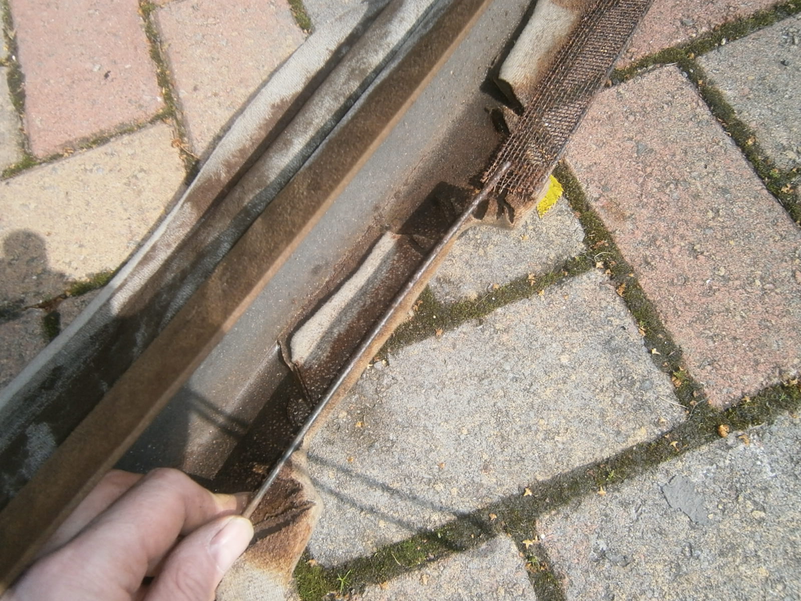
However, it is clear that this bumper is slightly different in form from my old. Firstly the "wings" that clip under the wheel arches are much smaller and don't occupy the same section as the previous bumper so I cant eliminate actual differences in the form.
 |
| Inside the wheel arch. The area covered by the "wings" of the old bumper is clear. The "wings" of the new bumper are much smaller and don't quite fill the space left when the old bumper was removed. |
In any event I removed the bumper again and trimmed the airbox duct side projections. I also examined the back of the bumper critically and found that the rear of the light unit moldings had a bumpy appearance which I filed flat. Finally, I extended the hole for the central bolt downwards a little further so that the bumper could be fitted higher. I'm not sure which of these had the desired effect, but on refitting I obtained a much better fit. Its still not perfect, but it is now acceptable!
 |
| Decent panel gaps rhs |
 |
| ... And on lhs |
 |
| Front view, bumper sits higher now. New number plate and frame fitted |
I still have to refit the pop-rivets into the wing sections and I'll do that when I can jack the car up and remove the wheels.