My System:
My attempts to start the rebuilt motor pretty quickly showed problems in both fuel supply and ignition. This post covers my attempts to sort out fuel supply.
In the Excel, the fuel system is contained in the boot in front of the spare wheel well and consists of tank, pump, flowlock, filter and associated hoses.
Hoses
The plumbing around my fuel tank has obviously been modified. Lotus use a special teflon fuel hose (6mm id) that is joined with brass or steel compression fittings 1/4bsp thread incorporating a compression olive. I don't know why Lotus make such a song-and-dance about this as it makes the system very difficult to modify or exchange parts. The unions should be available more cheaply from a plumbers merchants. In any event its a relatively low pressure system (<3 psi) and this seems to be overkill. The MGB in fact uses exactly the same pump and manages perfectly well with conventional fuel hoses joined using jubilee or ear clips. In my case many of the original Lotus hoses have been swapped for conventional pressure hose.
Filter
In 1984 Lotus didn't provide the Excel with an in-line filter, relying on the carb/pre carb filter, but one was introduced in '86 between pump and carbs. This was a sealed metal filter unit with threaded inlets and a replaceable cartridge element. Retrofitting this filter was recommended for earlier cars, and as you might have guessed, mine shows no sign of ever having been modified although a disposable filter was fitted between tank and pump.
Pump
The car should have an SU AZX1307 pump. This is quite a large unit and mounted horizontally. Mine had been replaced and the mounting modified.
Flowlock
The final component of the boot fuel system is the flow lock valve: The flow lock is a solenoid operated fuel shut off valve that stops fuel flow when the ignition is turned off. This prevents fuel siphoning from tank to carb, this is particularly likely if the car is parked nose down on a slope. Its an important safety feature- but sadly in my case there is no sign of it! In '84 this should be present below the tank. It seems the original component was a Tecalemit Flowlock- but its now obsolete. I will have to replace it's functionality somehow.
Removing the pump to tank link:
The first step was to disconnect and remove the battery- you really do not want any sparks during what follows. Just disconnecting the battery isn't enough because the tank is a big metal lump, you don't want to risk it accidentally shorting out (and sparking) the battery as you wrestle it out of the car! So after removing the battery, unscrew the banjo union to the base of the fuel tank. I used a tray to collect any spill- but in fact there was none! Apart from some old fuel (or perhaps water) in the lines the fuel system appeared empty. I therefore removed the outlet banjo union and its tank-to-pump hose. The parts list shows that there should be a mesh filter over this banjo... but I couldn't see one and checking later showed that it wasn't loose in the tank... its just missing! It also seems impossible to get a replacement as new banjos now come without a filter.*
*I have since found that Kelvedon Autos do one... but at £50... ouch!... Also there are motorcycle filters that ought to fit at only £3 each . I have ordered one of these from www.Norbsa02.freeuk to fit to my banjo. Alternatively the BSA C15 and B40 has an in tank filter that should fit although its not a banjo and will need some creative thinking to use it (feked.com)
I unscrewed the banjo bolt completely- it was full of muck and completely clogged! As far as I can tell the banjo is a 1/4 BSP thread 19 G with a 55 degree tooth.
 |
| Banjo bolt |
I removed the banjo union and lines- also very dirty and one of the crush washers was missing. This is the banjo plus the 180 degree turning piece that routes fuel flow back to the pump.
 |
| Outlet pipe- banjo union, pipe bend and connector. I think the connector is the original flowlock connection pipe but the olive on it has been removed. I will replace all this hose with new ethanol proof hosing as its gone hard and brittle. |
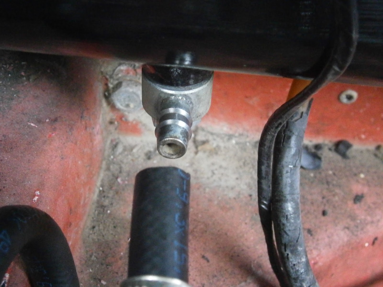
The first shock was the state of the connections- all unions were completely plugged solid with nasty brown gunk!
 |
| View along fuel pipe- nasty deposits furring it up! |
 |
| View into banjo union- tank side |
 |
| View into banjo union- hose side- completely clogged! |
To be frank I was shocked at the state of this system. The only good point being that all this was on the tank side of the filter (see discussion above) and none should have travelled through to reach the pump or block the downstream lines. I removed the pump connection and ran some fresh fuel through- lucky for me the pipes were not clogged and I was able to flush the old stale and dirty fuel out of the system. In the meantime I put all the clogged fittings into the sonicator to try and clean them up.
I then cleaned out the fuel pipes in the car using a temporary fuel supply connected through a new filter to the pump.
 |
Temp supply from can in boot- new filter in line
|
I had disabled the pump many moons ago at the start of my labours, because I didn't want it pumping constantly every time I turned the ignition on. So having remembered this I reconnected the spade connector it did spring into life and start ticking. I ran the first few mls or so into a tray to flush out the nasty brown gunk.
 |
| Testing pump |
 |
| Nasty old petrol running through |
I then changed the tray, tried again and it was running clear. I reconnected the lines and thought I could use this setup with a temporary tank to test starting... this didn't go well!! It revealed firstly that the fuel pump would only work for a short time and secondly that there was an obvious ignition problem. My exploits in chasing my spark are in another post (oil pressure and ignition): this one will press on with trying to sort the fuel system. Whilst I'm talking about this I should mention that the rubber sheathing on the Lotus hose has flaked off- which is pretty much par for the course in these older cars as it does get quite hot. However the internal pipes can be good for years after this (Lotusbits advice) and as new hoses are both expensive and difficult to attach to the carbs they recommend leaving these in place, but applying new external physical protection- such as an electrical cable cover? It occurs to me that there is a heat-resistant sheathing available for motorcycle HT leads which could be just the thing.
Removing the pump:
Obviously I can't leave the tank with this much crud in it, and I need to get a reliable pump so I set about removing them both - firstly the non-std fuel pump- easier to undo the three plate-mounting bolts as you can't get at the pump bolts.
 |
| remove 3 plate mounting bolts to detach pump. |
Once out, the pump is clearly not an SU unit and has the Mitsubishi symbol on the top. I found it could tick and move a little fuel but flow soon stopped and it never reached pressure. The mounting bracket has been modified by welding on an extra plate for this pump- The SU pump mounts to the plate in a different way so I will "modify" it back with a grinder and fit the right pump.
 |
This aint SU!!
Mitsubishi fuel pump- seems to work poorly and so I will replace it anyway. |
Removing the tank:
The tank is held in by a bolt each side into the body. The other end of this bolt is accessible from behind through the rear wheel arch and you need to hold it with a spanner in order to unscrew the bolt from inside the boot. This really needs two people or one person with freakishly long arms! I slipped a ring spanner over the back nut and let that jam on the body so I could unscrew from the front.
 |
| Tank LHS fastening |
 |
| Tank RHS fastening- note fuel filler pipe entering from top left. |
There was a lot of wiring around the tank serving the sender, HRW and pump- also a hanging white fastening which....
I think marks the site of the missing flowlock! This is needed as a safety feature (stops fuel siphoning down into the carbs when the ignition is off) but is prone to failure and has been removed in my car... It probably jammed on the muck from the tank.
 |
| Presumed site of flowlock device? Two mounting rivnuts in body and a loose wiring contact |
Having unscrewed the two tank-mounting bolts, its then just a question of removing the hoses (filler, filler vent, outlet already removed) which are held on with jubilee clips.
 |
| Filler pipe jubilee-clipped to tank inlet spigot. This is a stiff rubber pipe and hard to remove. I used silicone spray to help ease it up the spigot.- The vent pipe is attached here using a plastic tie to keep it out of the way, but the vent itself connects to.... |
 |
| ... the top centre of the tank where the vent spigot is located. |
 |
| ... and just pulls off. |
The clip on the filler pipe was easily accessible and unscrewed easily. However the pipe is wide, stiff and really tight on the tank filler spigot. I found it could twist it a little and by squirting silicone lube up the join I was able to loosen it- but it takes a long time and a lot of force in awkward positions!
 |
| Tank pulls forward to swivel it and twist to loosen attachment to filler pipe. |
 |
| Sender unit is mounted in top of tank |
 |
| I marked the wiring colours before disconnecting them. GR (rear) B (front) and GB (right) |
The tank was then removed for cleaning- note even though it appears that a tank is completely empty... there can be a surprising amount of residual fuel inside! If I was doing this job again I would think ahead more! I'd been convinced this tank was empty and I was somewhat embarrassed by the fact that it wasn't!
Having removed the tank I wanted to remove the fuel sender before cleaning in case it gets damaged. Its held on the top of the tank with a notched retaining ring. This needs to be tapped round to release unless you have the right spanner, and at 65mm its too small for the usual sender wrenches... I have been told a 3-legged motorcycle oil filter wrench will work well. I tried anticlockwise but it didn't want to go that way and surprisingly moved more easily clockwise.
 |
| Locked sender ring, ring rotated below retaining lugs- tap this round so... |
 |
| ... the indents line up with the lugs and ring lifts off. |
 |
| Sender beneath- just lever up gently. |
 |
| ... and can be lifted out of the tank |
 |
| Sender unit and float. |
The tank has been empty for years and so the sender has been simply hanging under its own weight all that time. It had stuck but it freed up with use and then moved smoothly. I checked that the resistance of the unit (between the two green leads) does vary as the float is raised- although strangely its infinite at both fully down and fully up. The float wasn't punctured so all seems OK to use it again I think but I will get a new gasket.
Cleaning the tank was very difficult- I de-vapoured it using a steam wallpaper stripper for an hour and then washed it internally using a 10% solution of Rustmaster Tank Kleen (Now POR I think). The tank is fairly large and has internal baffles which make my usual motorcycle approach of shaking with ball bearings impractical. I shook it as best I could and then poured out the nasty cloudy gunk. I rinsed thoroughly in water until it ran clear and scraping the bottom with a rod no longer picked up any gunk so it must be better.
The tank is still a little rusty in the centre section- although the endoscope showed the extremities were better. I would usually soak in Deox-C overnight to remove rust, but the baffles do mean that loose rust tends not to travel the full length of the tank anyway. In view of the difficulties in handling the tank I decided to forgo this and just dry it out after the rinses.
There was no significant rust on the outside of the tank but hey; ... what do you do while you are waiting for hoses and connectors? ... I repainted it!

New Pump
The new pump from Burlen is a AZX1307EN pointless electronic pump. It should be pretty much fit and forget (... hmmmm!!!). The unions weren't supplied with the pump. I have an old brass pump union from my Elite- this is 3/8 BSP tapered thread - but the thread in the pump is BSP parallel. Tapered threads are designed to seal actually on the metal thread whereas parallel threads always require a sealing washer of some description.
 |
| Lotus Elite SU pump fitting- note 90 deg configuration and taper in threads. Perhaps these only seal well when they are new- remains of sealant still in thread grooves but I never found this to be satisfactory and replaced it with the MGB banjo union- a trick I was hoping to repeat on the Excel. |
The important point is that the Elite fitting lacks a flange so was never able to (or designed to) compress the pump O ring and the thread sealing activity (even with sealant or tape) was always inadequate. The tapered union is supposed to seal primarily via the threads- but in my experience it never worked! Its possible it would be better if the female thread were also to be tapered (I think there is an international agreement that states they should always be parallel) or if the union were new? I am very anxious to avoid this leakage again and I definitely think a 3/8 BSP parallel fitting with a flange + O ring or washer is a better way to go ... After all this is how the pump is designed and I would rather work with it than against it! I have ordered a pair of MGB/SU pump banjo fittings which I hope will achieve this and did eventually solve the problem in my Elite. However I was expecting the unions to the pump to be 90 deg bends (as in the Elite) but to my surprise the Excel has straight in-line unions and so the banjo approach might not be suitable. As a second possibility I have also ordered some straight brass hose tails (3/8BSP x10mm) and a 3/8-1/4BSP adapter plus 1/4BSPx8mm hose tail from BES plumbing supplies. This should cover all bases!
I have given the question of how to fit replacement filters a good deal of thought. In my car a disposable in-line filter was installed between tank and pump. Given the state of my tank this seems really sensible (to keep muck out of the pump)- but, its usually recommended that the filter is fitted
after the pump. This is because if the filter should clog and the pump runs dry, then an SU pump will stall in a "current on" position which will of course eventually damage it. However, the tank originally had an internal tank banjo filter- obviously this is also before the pump and so the same argument presumably applies to that- and blockage here probably explains why the SU pump was changed. If I can I will reinstall an in tank filter but as its obsolete I may not succeed. If I can't get a tank filter then I think fitting an easily serviced, in-line filter before the pump is still a sensible move
provided that it is easy to inspect, service and change regularly (and indeed very frequently) until I can confirm that any flow of sediment exiting the tank has stopped. In order to make this servicing simpler I think I should also install a fuel tap or flowlock between tank and filter so that the tank can be isolated easily whenever the filter is serviced. Finally I can re-route the plumbing if and when sediment flow ceases and reposition the filter after the pump at a later date.
Replacement hoses seem to fall into two possibilities- modern braided teflon hose joined via AN6 unions. These would need a 3/8BSP to AN6 adapter to screw into the pump and a variety of unions/adapters and possibly new filters and flowlock fittings (1/4bsp to AN6) with AN6 unions. This will be quite expensive. Alternatively- I could use ethanol-proof fuel hoses fitted to pipe tails and device unions with Jubilee clips. This is a versatile system and should cope with this low pressure fuel pump.
Consequently my plan for reconnections goes:
Tank banjo (with in-tank filter if I can get it), 180 degree turning piece, Fuel cock, Filter, flowlock, pump. However since a flowlock equivalent is around £45 I will wait for a while to get that and use the fuel cock if I end up parked downhill.
Refitting
Tank filter
I bought a BSA in tank filter from Norbsa02. This was around £3. It consists of a plastic framed gauze with a 1/8BSP thread at the base.
 |
| BSA in tank filter- 1/8 BSP thread at base. |
It would be great if I had a 1/8 BSP tap but sadly I don't. Luckily this size is very close to 3/8 BSF so it was easy to dress the plastic thread with a 3/8 BSF die nut
The banjo bolt then needed to be drilled out to 8.5mm and tapped to 3/8 BSF
 |
| Tapping the banjo |
Finally I had to drill out the top 4mm of the bolt to 10mm to allow the BSA filter to sit inside.
 |
| Banjo tapped internally and top-drilled to 10mm |
It then screwed up neatly onto the new thread.
 |
| Filter screwed in. |
I refitted the sender turning anticlockwise to lock.
I used Wellseal on the upper surface of the gasket as this looked a little perished.
In fact refitting the tank wasn't too difficult. My suggestions:
1. refit wires to sender unit before installing tank-
2. don't forget to restick the felt protection to the tank
3. use silicone spray on filler spigot and inside filler hose to help it slide in.
Apart from that the tank fitted relatively easily. Whilst I was in the boot I replaced the boot edge seal and removed and repainted the battery carrier. Then I fitted the pump and rerouted the hosing and fittings.
Fitting the Pump:
I removed the extra welded parts that had been fitted by the LBPO and fitted the new pump to the bracket. Screwing the plate/pump assembly back onto the three studs showed that it tended to sag at an angle which meant the top of the pump could contact the fibreglass body. I suspect this will lead to noise and vibration so I used some washers under the bottom mounting point to lift the pump to a more horizontal position.
I tried to use the MGB banjos but those I had bought lacked the recess for the fibre washer on the exterior side. This meant that the fibre washer could wander around a little, and as the sealing ridges are quite narrow, the net effect was that it leaked like a sieve! I machined out a recess to hold the washer and soaked the fibre washers in oil for 24hrs to improve their flexibility before refitting. Although this didn't leak, I found that the 90 deg bend imposed by the banjo unions was unsuitable for the Excel where the hoses need to enter in line.
I then used conventional 3/8 to 1/4 BSP thread adaptors fitted with 1/4 BSP 10 mm hose tails- all parallel threads. The adaptors were a little too small to cover the SU O rings fitted to the pump completely- but they did cover enough to give a good seal.
I refitted the tank exit banjo using new 1/4 BSP 1.5mm thick copper crush washers. It was easier to fit the hose to the banjo before tightening the banjo itself onto the tank so that it could be swivelled to a convenient location. I used 10mm ethanol resistant hose to connect the tank to the U bend tube and a short length of 10 mm to the shut off valve. This was fitted with 10mm and 8mm 1/4 BSPP hose tails to act as an adapter and allow me to use 8mm tubing from this point to the pump.

Fitting 10mm ethanol resistant hose to the banjo swivelled forward before tightening
From the shutoff valve 8mm tubing connected to the filter and from that to the pump. All hoses were mounted using rubber lined 15mm id P clips. These were originally fitted with pop rivets which of course makes them tricky to remove if you wish to reposition the hoses- as I will need to do! I therefore used M5 rivnuts (as Lotus used for the Flowlock) so that clips are all removable.
Although I have now received my replacement flowlock I don't want to risk this getting plugged with any of the initial sediment runout from the tank, so I have fitted a temporary fuel tap in its place and a filter between this and the tank. Once I am sure sediment flow has ceased I can reposition these items; I will install the flowlock where the tap is currently positioned and reinstall the tap between the filter and the pump.
 |
| Overview of temporary fuel setup. |
 |
| Tank exit banjo: 10mm hose into Lotus U bend; P clips to retain hose at rear. Note fuel pipe to carbs exits boot below tank. |
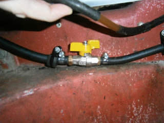 |
| 10mm hose from Lotus U bend to in-line tap fitted with 10mm input and 8mm output hose tails |
 |
8mm hose from tap to in-line filter (replaceable element) and 8mm hose onwards to pump position (not yet connected). P clip holding filter.
I will leave all these filters etc in position until I am sure that sediment flow from the tank has ceased- or I am confident that the filters are protecting the system. I don't want to risk gumming up the flowlock and finding the car suddenly inoperative.*
|
 |
| Pump connected- all jubilee clips fitted. |
 |
| I had removed the tank in order to fit my replacement sender unit. |
I have now fitted a replacement sender unit. This has a working "low fuel" warning switch** and since I do not want to fuel up the tank until I have done some more work on the exhaust (which will involve a blowtorch on the seized nuts!) I don't want the light coming on and staying on everytime I turn on the ignition. I don't want to have to fiddle about in the narrow gap above the tank trying to connect and disconnect the spade terminals on the sender so I have introduced a bullet connector in the G/R lead that feeds the low fuel switch so I can disconnect it for the time being.
 |
| New (replacement) flowlock complete with 1/4 BSP connectors. I will install this later. |
**... Oh no it doesn't! Despite the assurances that this unit had been tested at Lotusbits... it doesn't work! The low fuel light remained resolutely "off" when the ignition was turned on- although as before it activates if the terminal (GR wire) is earthed! I shouldn't have believed them and tested again before fitting! Ah well- its in now and I don't want to pull the tank yet again so I will live with it.
Having reconnected the pump, I did go ahead and put some fuel in the tank because its so much more convenient that using loose fuel cans! The first 2-3 litres was unusable probably because of an upstand by the banjo union inside the tank; the fuel level has to pass this before it can flow into the tubing. Above this fuel flowed well and was visible passing through the filter. I had expected a lot of sediment but none was apparent. I will keep it like this and rearrange later to introduce the flowlock. luckily no leaks. I have however now observed a dripping inside the carbs whose cause isnt clear- possibly an error in the rebuild or perhaps the new pump is supplying excessive pressure. That's the easiest to fix as it would mean I don't need to strip down the carbs again (!) but I don't have a fuel pressure gauge so ordered one and will check next week.
* Note added later... Eventually I did get this car recommissioned and up and running. However it managed less than 5 miles before it developed a terrible misfire and lack of power. All features pointed to petrol starvation and eventually I found profound blockages in both carbs around the needle valve filter. The blocking material was a fine rust that had passed through not only the in tank filter element but also the in line filter. It was apparently stopped in the carb fuel inlet ports by the needle valve filter tubes- a part that is now obsolete. Its effectiveness here as the only functional filter in the system leaves me wondering why it was ditched? However it may be that the sediment collected here simply because the nature of the needle valve means that flow is a stop-start process in this area allowing silt to settle. It was a very fine deposit and I didn't find any blocked jets or passages in the carbs when I cleaned them. This was a surprise to me as the tank had appeared very clean after my attentions. I think the best way to stop a tank rusting is to keep it full of fuel and the fact that this one had stood almost empty for so long since my cleaning probably allowed fresh rust to form inside it. Anyway I ran a litre of fuel through the new filter before connecting hoses to the carbs again to make sure that everything past the new filter was flushed clean. However after a clean motor function was restored.
 |
| Repositioned filters incorporating an extra disposable paper element type. |
In order to prevent this happening again I installed a third filter- this time an in-line paper element disposable type by Mann. This meant re-positioning the mesh filter which is now functioning as a pre-filter ad once more I will install the flowlock if/when I am convinced that sediment is no longer a problem.
NOTE:
I later found this guide to removing the tank on the forum. It recommends removing the top end of the filler pipe which might be more sensible as refitting the bottom connection inside the boot is awkward although the silicone lube spray helps an awful lot!
Fully drain the tank first. The easiest way is to disconnect the out line from the fuel pump and to pump it into a clean appropriate container.
Disconnect the vent lines.
Disconnect the sender wires - small clip at top of the tank.
Take the fuel filter assembly off its mount.
Undo the nuts/bolts at each side of the tank. Two person task as you have to hold the bolts with a spanner at the rear of the wheel arches.
Take the fuel filler cap off, along with the rubber gasket.
Then unscrew the metal plate under that, along with any sealant on it.
Wiggle the tank out, carefully avoiding damaging the boot lid, weatherstripping etc.
Empty the last from the tank into another container.
Remove the fuel pick at the rear bottom of the tank. Clean this and ensure it is not blocked or bent etc.
Check all vent lines are clear.
Then reassemble!