Search for tasks- type in keywords

Thursday, 9 July 2015

Oil Gallery

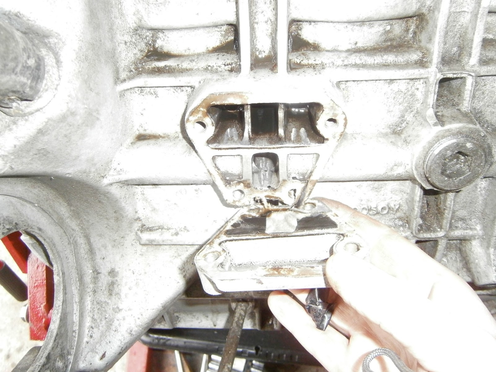
The oil gallery locate don the side of the block is retained by only 4 bolts. Since I'm cleaning and stripping this seems a likely place for crud to build up so I decided to remove it and clean.
Note tape over oil pressure take off- applied before I steam cleaned the block.
The gallery cover is held by 4 bolts, the two longer ones are at the top and the shorter at the bottom.


Cover easily removed.
There wasn't a great deal of muck underneath but certainly some, so I cleaned out the cavity, removed all the old gasket from block and cover and degreased and cleaned the cover. I then refitted it without a gasket simply to cover up the cavity and keep out the much until the engine is finished and the rebuild starts when I will install all the peripherals properly..

Auxillary Housing and Oil Pump

I think I have mentioned this unit before- it simply bolts onto the side of the crankcase. The bolts though are different lengths so I will need to sort these out carefully when refitting as I have forgotten what goes where!
Auxillary housing removed, Note cambelt drive pulley 
at front and pump housing at rear. Drive shaft visible 
though centre of body
I have no reason to doubt that this pump works fine- but I have no reason to know that it does either!  I decided to take it apart and check it for wear. The pulley nut (Allen screw) was removed whilst the pulley was held using a wooden dowel through the pulley holes to prevent rotation. The pulley could then be removed with a two legged puller pressing against the pulley screw which was reinserted about half way to prevent damage to the threads. Make sure that pulley extraction isn't prevented by this bolt as its drawn off the shaft- obviously if this happens tightening the puller won't help so check as you remove it. I am told that this removal should have needed heat as the pulley ought to be loctited onto the shaft. I didn't find a problem but its always possible my pulley hadn't been fitted properly in the first place. 
Insert wooden dowel through pulley hole to prevent rotation before unscrewing centre bolt and special washer beneath


Once pulley removed the Woodruff key is eased out...

And the circlip behind it can be removed

At the other end of the unit, the pump housing simply
unbolts from auxillary housing body


Revealing the annulus and rotor keyed to the shaft.
This revealed the working of the pump, a rotor keyed to the centre shaft around which is spun an annulus, the complex interlocking lobes squeezing the oil to provide pressure and movement in the system. Everything looked OK but I wanted to check it. This was quite difficult as the manual gives four determinants for wear- none of which were immediately obvious and all require detailed and accurate measurement.
Rotor/Annulus tip clearance- as the rotor spins the gaps between its teeth and the cutouts in the annulus narrow... this should be in the range 2-6 thou (0.05-0.15mm) but as its a highly curved structure a feeler gauge is useless. I took it to a local engineer/modelmaker who had some gauge pins. Sadly the smallest was 6 thou so all I can say is that the gap is smaller than that. As an alternative I measured some kitchen foil. I only have a metric micrometer but in my hands the foil was 0.03mm thick. I cut a small sliver of this and inserted it into the bottom of one of the annulus cutouts. I could then turn the shaft (and thus the rotor) until the gap closed. Even at its closest I could still pull the foil out smoothly so my estimate of this gap is between 0.03 mm and 0.006 inches or between 1-6 thou imperial. I think this is in range.  
Annulus End float. I had expected that this meant that the annulus would be thinner than the housing into which it fits by 1-3 thou permitting some axial lengthwise movement of the annulus along the shaft of the pump. This can be measured by fitting a straight edge across the housing and probing the gap with a feeler gauge. I was therefore very surprised to find that the annulus actually projects beyond the housing and the gap I detected (1.5 thou) was between the ruler and the housing itself! Having checked on the forum I was advised that this gap should be measured with the gasket in place and adding that showed that there was a clearance of 2.5 thou between the annulus and the top gasket surface and so I concluded therefore that this measurement was still in limit.

Straight edge across the annulus with
gasket in place
2.5 thou gauge slid smoothly
between annulus and straight edge


Annulus Housing clearance. This is the radial clearance between the diameter of the annulus and diameter of the housing wall- and this should be 7-12 thou. However this should be easily measured using a caliper to take the external diameter of the annulus and the internal diameter of the housing. Subtracting these should give the housing clearance. 


Its tricky to get accurate measurements with a caliper, but I don't have a micrometer big enough. I took 5 separate measurements and got a range of 5-10 thou and an average of 8.5. This puts the wear within limit.

Rotor End float- I don't know what this is! The rotor is keyed firmly to the shaft and can't move separately, however auxillary shaft end float (given elsewhere in the manual) isn't the same as rotor end float so I'm mystified. However Annulus end float refers to a radial clearance so perhaps rotor end float is also radial? However as its fixed to the shaft I can't see how this could be measured. 

Oil Pressure Relief Valve This valve is non serviceable as far as I can tell and is built into the oil pump housing. The valve consist of a spring loaded flap. I checked that this will push down with pressure from a screwdriver and then flushed the valve through with WD40 to shift any muck that might be jamming the valve.

Inside Annulus housing. Oil pressure relief valve at 3 O'clock, the sealing plug visible at the bottom of the opening. The bypass tunnel it communicates with is at 11.00

Overall, of those parameters that I could measure all seem pretty much in permissible ranges so I'm going to rebuild and refit the pump with new gaskets and oil seal. I'm also replacing the pulley circlip in case the old one was loosened during removal.

Reassembly
The order for this job has to be oil seal, shaft, circlip, pulley, pump  and pump housing. This is so that all forces exerted say in seating the pulley, can be transmitted down the solid metal shaft and not onto the pump housing.  The oil seal simply pressed in to the housing using a seal installation drift. I used a Draper tool but a socket would do.

Oil seal installed. Note drilling opening into space beneath seal at about 1.00 O'clock
The seal didn't bed right down onto the body which worried me until I checked the pre-strip photographs, the old seal was installed to the same depth (app 1mm below the outer edge of the recess) as well. I observed a drilling and presumed oil-way that opens into the space beneath the seal and which would be blocked if the seal did bed down fully. I suspect the is the reason. The new seal is a double lipped  type and the old one was only single lipped. I'm guessing this means you could use either.

Apply lots of assembly grease to the auxillary shaft especially over the journal areas and around the seal lips. I use Red assembly lube as its cheaper than Graphogen. The insert the shaft from the pump end right through the seal and fit the circlip to the pulley end. Dont try to open the circlip up in order to slip it over, this will bend it too far and distort it, instead push it onto the shaft end and tap it over with a mallet. It will then slide down the shaft and clip into its groove.


Insert the Woodruff key taking care that it is centralised and slips fully into its slot. Support the pump end of the shaft on a wooden block and line up the pulley keyway with the shaft key. Start the pulley gently by hand then tap home using a socket that just slips over the pulley hub. The manual calls for Loctite on the pulley. I didn't use any- I reckon its not going anywhere! It can't go backwards owing to the circlip, or forwards because of the nut and can't rotate owing to the key. I suspect I may well will be doing this job again and loctite will simply complicate any future strip.

Starting the pulley. Note assembly grease on shaft

Pulley fully seated onto circlip


I could then fit the special washer and hex plug screw into the shaft end, hold the pulley with a dowel through the pulley holes and tighten the bolt to the correct torque. I didn't have a torque wrench hex bit at the time but I've got one coming and I'll check the torque before I refit the unit.
The pump was then reinstalled using a fresh gasket. This is a plastic gasket and is installed dry. It looks like it will go in any way round but in fact it will only fit in one orientation. The rotor has to be centralised in order to fit so I used the housing to jiggle it
Fit Gasket dry in correct orientation

Fit annulus and centre using the housing without regard to the bolt holes, then remove the housing and line up the pins and holes without moving the annulus, Grease with assembly grease inside and around edge of annulus...

... before offering it back up in the correct orientation. It will be necessary to lift the pulley off the bench so that the shaft can drop back allowing the housing to fit.
Finally the bolts were inserted and torqued up diagonally to 7ft/lb. The last step was to clean the gasket mating surfaces and then wrap the pump for storage before I can refit.

Wednesday, 24 June 2015

Moving on...starting to strip the motor!


Hello long lost follower! I have at last returned to the Lotus Excel rebuild. I have cleared the various motorcycles littering the garage and now have room to move. This is my lotus experience- partly for your amusement but mainly for my own records.... So to recap... the motor I got to replace the one in my car was a used item. It had been stored for some 10 years. The guy storing it was an experienced engineer of the agricultural school. He had partially dismantled the motor to check he wasn't storing a dud (sensible) and assured me it was OK. Although it was back together it was only loosely assembled and so I didn't know what I would find.

My general plan was to inspect, renovate or renew where essential and then rebuild and reinstall. I started out with the best of intentions to fully rebuild, swap and restore- obviously its easier and more certain to simply replace everything and produce a nicely reconditioned motor - but that has proved prohibitively expensive as  even gasket sets are coming in at app. 200 quid for upper and lower sets, so I will settle for a working engine in good "used" condition- I hope I can at least achieve that. The aim is to check and reuse  components wherever possible without a lot of new or recon parts. Trouble is this is not a new engine and there will be wear; so the question is how much wear is too much wear... and deciding that thorny question is going to be my problem!   I am on a tight budget so I don't want to do any unnecessary work.

My rough plan of attack :
1. Clean motor as best I can plugging any exposed openings. I will use a steam cleaner/wallpaper stripper in combination with spray-on degreasant and vigorous brushing.
2. Remove head, remove valves and check for guide wear. Unless significantly damaged I dont wish to replace valves or springs, but just clean and regrind in the valves.
3. Check piston heads, fit clamps and check rotation and bores.
4. Remove tensioner, water pump and oil pump. Check all and if necessary rebuild or replace with renovated units.
5. Remove sump and clean out, check condition of big ends and mains as best I can, hoping to avoid any significant work on the lower end as I'm assured the motor is OK.
6. Replace front and rear crankshaft oil seals and any seals in the camshaft housings.
7. Reassemble with new gaskets.
 I have  already noted that there are a lot of nuts and bolts missing as the motor has only been loosely reassembled for storage so I will need to get quite a lot of those.

That's the plan anyway, I'm sure events will force alterations.

First job was to remove camcovers, camshaft carriers and head. The Cam covers were held on by only 1 screw each and this only hand-tight so easily removed. Luckily the cams had been oiled and weren't corroded even if everything needs a clean.  When removed the top of the head and valve gear was visible, only two valve tops had shims- doubt that this is correct but I will need to check.

One cam cover removed
Then the second. Note only 2 valves have shims? Sparkplug holes were stopped with rubber bungs after oiling for storage. Most cylinder stud nuts absent


Cam carriers easily removed, don't
look too badly corroded


I removed the inlet manifold fairly easily but access was blocked to the central two lower nuts on the exhaust manifold. Well in reality there was probably access enough to get a limited turn on them but in my case both had been rounded off and were impossible to move. They would need to wait until the head was removed.The head was held on by only two nuts, easily removed and then it lifted off. Although this improved access to the lower manifold nuts they still couldn't be turned so had to be ground off before the manifold could be removed.

Exhaust mating flange on exhaust manifold
stud OK but both bolt holes are opened.
The manifold was damaged around the exhaust flange mounting where both bolt holes had been cracked open. I suspect this would still clamp and seal but as I will be stripping ancillaries off the motor currently in the car, I am expecting that this will simply be replaced. Most of the manifold nuts were corroded and unscrewed from the head as a stud. I tried to free these up on the bench by holding the nut in a vice and screwing two nuts onto the other end of the stud.. You can then then heat the nut and try to unscrew the stud using one nut unscrewed against the other. Only one worked  so its time to start listing parts needed for replacement. I am intending to replace most nuts and washers so its going to be a long list!

Having removed the head the pistons and any visible p[arts of the bores looked OK (below) but before I could turn the motor over I had to fit the liner clamps. I got the clamps laser cut in mild steel using CAD drawings from the lotus forum. The set of 5 includes 2 with slots to fit around the alignment pins in the block.
Original is a pdf and processing has removed much of the contrast-  but you can download it from the same place I got it! https://drive.google.com/file/d/0B2nifoCpaFSfNTAwM2Y0N2ItODRhNC00NTM0LWJkZjUtMTc3OWNhMzA0ODZk/edit?pli=1
I made the spacers using 2.5 inch lengths of galvanised steel cable conduit from an electrical wholesaler, add 10 M12 washers and nuts and they work beautifully.

Block with liners installed, piston heads were
undamaged
Slots in two clamps accommodate locating dowels


The motor rotated very smoothly, the bores looked great which was a nice surprise. There was no top ridge and they still have a nice cross-hatched and honed appearance. The pistons slide smoothly and although there was a little rust this was more of a discolouration and limited to the top of the cylinder above the ring travel range. It all looked clean and functional with no signs of valve impact on the pistons or damage to valve edges beneath the head. I sprayed the bores in WD40 and wiped them out to keep clean and prevent corrosion setting in while I have the bores exposed. All promising, I had intended to remove the crank and recondition but everything looked far better than I had expected- maybe I will get away with some fresh lube and a reassemble? I will check that all pistons rise to the same height above the block as differences might indicate conrod damage (later post)


Head. Looking at the head the valves all look in need or a decarb and a clean but they appear undamaged. Their heads seem to sit at different heights which may be significant, I will investigate more closely. I think its going to be worth removing the valves to check for side wear in the guides but until I strip them out I dont know what will be needed in terms of head recon. I'm not after building a race car here- just a solid reliable road car- well as reliable a Lotuses ever were... I will post separately on the stripping etc when I get down to it (later post)

Ancilliaries.
It was my intention to recondition or exchange most fittings on the motor- the main ones being waterpump, oil pump and chain tensioner, however this  was starting to look expensive.

Water pump was only held on by one bolt, and that was loose! Easily removed and cleaned. I cant find any wear in it but I may simply send it in for an exchange unit. The price isn't that different from buying a rebuild kit and as I don't have access to a workshop press, I doubt I could replace the bearing myself anyway.

Water pump in situ
Water pump removed, chain tensioner still in position


Oil Pump - again this had been previously removed and was only loosely held on. I can't see any wear in it as the shaft looks sooth and firm, not sure how to test this for wear anyway. I will need to investigate whether this can be DIY rebuilt. So far I havent disturbed the impeller pump section (later post).

Oil pump in position, driving pulley

Oil pump removed- from underneath

Oil pump block mating surface, not too dirty, some sludge for removal visible inside.


Belt Tensioner - Surprisingly this had not been previously removed and all bolts were tight. The spring was extended and had jammed against the moving pivot. Idler pulley bearing didn't rotate and had some surface corrosion.

Belt tensioner as found, some corrosion on tensioner bearing


Belt tensioner as found.

Note tensioner has popped out of its housing, should be
retained by 3mm pin, teflon piston pretty scuffed
Note lack of locknut on adjuster, stack of washers replacing spacer on lower bolt between tensioner body and snubber arm
The tensioner was retained by a large  nut threaded onto a stud in the engine block and fitted with a spring washer, washer and spacer on top of unit. A second bolt passed through the tensioner. Both the nut and the stud have a spacer behind the tensioner between it and the snubber arm, however the correct spacer was missing from the bolt and this had been replaced by a stack of washers. (see above).
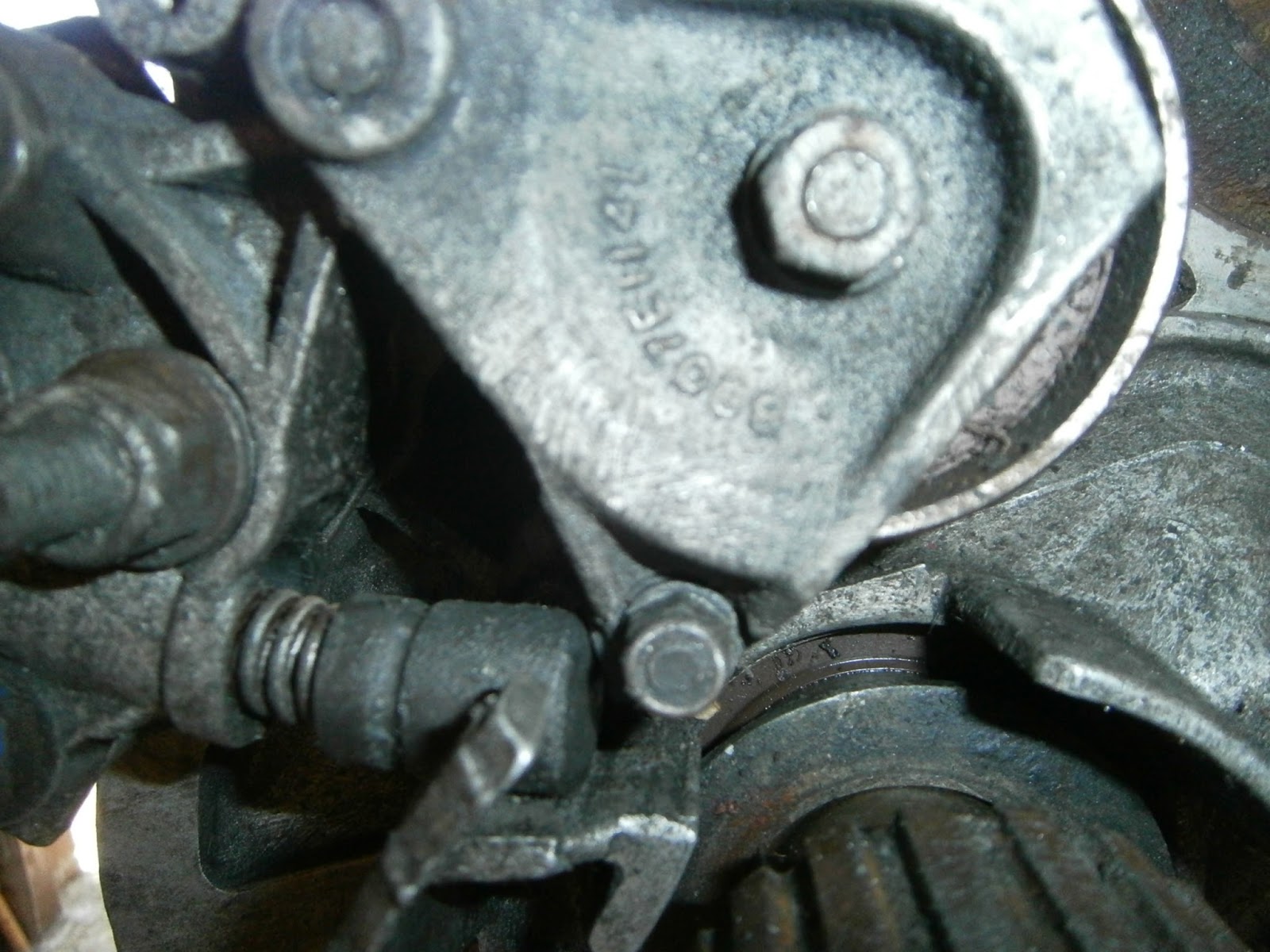
Having removed the tensioner the pulley bearing was released by undoing two bolts, one through the centre of the bearing and a smaller bolt beneath (see below)
Tensioner removed, spring and piston could be removed from
 tensioner body. Note central bolt, removed to free pulley,
second smaller bolt bottom Right.Pivot pin is at the top.
Smaller bolt could be accessed with two 1/4 drive sockets.

 Once freed from the tensioner the pulley bearing could be examined, it did rotate smoothly, without roughness but the rotation was very stiff. I decided to replace it as the tensioner  would normally receive attention when a new belt is fitted anyway - as will be done eventually. I therefore bought an overhaul kit comprising the earth wire (missing from this unit), pulley and piston which was badly scored (below) and bushes for the pivot pin. I will need a new locknut for the adjuster  which is an M18 ringnut with 1.25 pitch thread; it seems remarkably hard to find a replacement at a reasonable price. I will post a blog of the rebuild later, in the meantime all the components will receive a thorough clean and I will try to find service limits for the spring usable length. I don't want to assemble the tensioner and then store it under tension in case this  scuffs the new piston so I will probably store the cleaned tensioner and any new parts until I am closer to reassembly.
Piston, double spring and adjuster screw as released from tensioner body

Sunday, 26 October 2014

Clarke Engine Tear down stand


Well not much been going on with the Lotus. I did however see some bits on Ebay and judging that was too good to pass up on I bought myself a leather interior and a new motor. I don't know how badly my motor is damaged but at the best maybe I will be able to swap the head, at worst the whole motor, but at least I was assured that the replacement is in good condition and has never thrown a cambelt- so that has to be good news.
Anyway having dragged the lump back from Devon I needed to mount it for easy work and I decided to use my Clarke engine stand- this is the basic model CES500A (pic from machine mart catalogue):
If you know these stands then you will know that they mount the motor by means of 4 tubular round spigots welded to box section  arms that themselves move on a rotatable mounting cradle. Bolts pass through these spigots and screw into threaded holes n the block- so you need bolts of the right size and length to match those holes already present in the block. In the case of the 912 these bolts are M10. The ID of the spigots is about 16mm and obviously 10 mm bolts are thinner  than this and so would be supported only at the rear, where their heads enter the box section, and their heads where they enter the engine block.  I have never liked the idea of loose bolts slopping about inside these spigots which I think will strain both the bolt and the engine mounting, so I bought some 16 mm OD 10 mm ID tubing from ebay. The sizing on this wasn't so accurate so I had to bore them out with a 10 mm drill to take a 10 mm bolt,  and turn the tube down on the exterior until it would slip into the mounting spigots. However using the tube allows the bolt to be supported along practically its whole length. I cut 7 cm lengths of this tube and it then slotted into the stand down to the first weld (joint to box section) and projected from the spigot far enough to compensate for the thickness of the flywheel which was still fitted to this motor.


The Clarke stand is maybe the cheapest of those around and I found that its arms just weren't long enough to offer any choice of the stud holes that could be reached. There was in effect only one way of mounting the motor so I determined which holes would be used and cut some 10 mm bolts to length allowing for stand spigot, spacer extension and hole depth before  fixing the stand cradle to the motor and then hoisting the motor  up to stand height to allow it to be mounted.
These are the only 4 holes that this stand can reach, 10mm bolts in each but they do need to be different lengths. Note inserted tubes slipped into mounting spigots on stand to suport the bolts.


My motor is likely to rest in this position for some time so I also cut a supporting leg from some joist timber and fitted this between the stand base leg and packing on the sump to provide some added support and hopefully avoid excess stress or bending the mounting flanges.

Hopefully this will do it- as the stand is mobile I can also wheel the motor conveniently (and VERY carefully) around the garage until I get around to stripping it.

Wednesday, 9 July 2014

Jacking points


Well having solved the  wheel nut problems the next thorny question is how to raise the car? A search of the excel.net shows that this is a perennial problem - largely because its hard to believe that GRP is so strong that you can jack on it. Well I know that you can as I did so on my Elite but even so I'm not greatly happy about supporting the car for maybe a couple of weeks in this way as the chassis and engine/transmission are effectively just hanging from the body by their bobbins! ...And as anyone who has ever been suspended from their bobbins can tell you it can certainly make your eyes water!

As I can gather from the forum the threads suggest
1. Jacking point metal plates will rot away leaving the jacking points unprotected. Dont use the scissor jack IF this applies (probably OK if jacking points still sound).
2. Don't jack under the jacking points with anything else unless you have packing- piece of wood to spread the load.
3. Jacking is best done under the front cross member to raise both wheels at once but access for a trolley jack is difficult unless you can drive onto some blocks or a ramp first.
4. Jacking at the rear can be under the diff (not really recommended unless for very brief lift and onto stands) and it could do damage. The suggestion is to use the lower diff frame mount although I'm not sure where that is!
5. When jacked up, get the  car onto axle stands placed either at a) the jacking points with padding b) under hubs/suspn arms with padding c) a wooden cross beam going across the car and taking the weight ....?

However despite this wealth of advice there isn't a single diagram, for instance where should this cross beam go? Can you still jack under the jacking points using wooden packing if the jacking points themselves have vanished? If the GRP is damaged at this point does it matter in terms of structural solidity of the car? Without diagrams or pictures its really difficult to know where to jack/support if not at the jacking points- and as I found out, for me this is potentially a problem.

My rear offside tyre has the worst leak- so first thing was to check out my jacking point for that wheel- no plate and a nasty shock!
Rear Offside jacking point- no plate and a nasty hole!

This is very worrying with a hole- circular mark which can be traced right around the jack point suggests a previous jacking attempt with an unprotected trolley jack (cup support) at this position. Clearly the box section  has been stressed away from the strong point and cracked- but is this a serious problem and can it be repaired?


Rear Nearside jacking point- missing the plate but at least its not holed.
Time to look at the front points:
Front offside
And the final...
Front nearside, plate still present
Front nearside seems the best preserved with jacking plate still present but covered in GRP goo

Its not immediately clear to me whether these points are usable (even with timber packing pieces!) and I certainly don't want to crack the body. I think all bar the rear offside should be OK so perhaps some tentative jacking is needed to test this.  My biggest worry remains the rear offside- which is of course the one I need to get to first! 

Its not clear how jacking points should have been attached but perhaps they were just stuck on with GRP- all odf the sites are surrounded by what looks like isopon but was this a factory installation or a later replacement? Another mystery is that all of these jacking points have a central circular indentation that and most seem to have a red cup-like feature inside this. I had though that this is part of the reinforcement plate- but a look at the new plates on SJSportscars shows that in fact these simply have a hole that would locate directly over this red feature. So what is it exactly and is it load bearing?


Saturday, 5 July 2014

Locking Wheel nuts

The wheels fitted to my Excel are clearly from the Toyota parts bin. They are the same as those fitted to the Celica Supra and probably others. They were however offered as genuine Lotus originals and to prove this they have a nice (flimsy plastic) Lotus centre cap. I quite like them although I'm not sure if they were optional or standard on the Excel. The sales leaflet I have from 1984 shows them fitted and doesn't mention that they were any "option" as such.

Lotus publicity flier 1984

Anyway my problem wasn't the wheels; it was the fact that someone had thoughtfully fitted locking wheel nuts and then (not so thoughtfully) disposed of the socket key/adaptor. Unfortunately only one tyre holds air; I have slow punctures on 2 wheels and a not so slow puncture on one other. The tyres will need fixing. I'd rather fix the punctures as this size is now unobtainable so changing just one or two isn't an option- I will eventually need a full set of substitutes before I can drive with safety- (but that's another story). For the time being-just pushing the thing around the garage holding air will be good enough!  Anyway in order to sort this the wheel shave to come off.

 I've been here before- it once took me three days of hammering to tap a set off my Escort. In the process both wheels and my hands accrued a considerable amount of collateral damage and I didn't want to do that again! Of course, I do have a set of "locking wheel nut removers". I put these in inverted commas because they seem to be of ornamental value only. They failed with the Escort and they failed again here. I reckoned I needed another approach.

Firstly, I took some Blu-tack and warmed it before pushing it firmly into the socket head of one of the nuts. When pulled out this gave a template for the size and position of the indentations into when the teeth on the missing key should fit. I then found a socket that fitted over the nut centre but whose rim overlapped the position of the key holes, and then I transferred the tooth pattern to the outside of the socket using a felt tipped pen. Finally I used a grinder to remove material between the "tooth" positions and hey presto! A rough and ready key.
Anyway, I fitted that to my impact gun and away we went.- Well I say away we went but it turned out these nuts were tighter than buggery, and took a hell of a long time to loosen- but eventually they did and I was rewarded with that lovely soft "Whirring" sound an air wrench makes when it wins and the nut finally loosens! Well the makeshift key was pretty much destroyed in this process (pic) which was sad as it was a fairly new socket. However,  it was cheaper than getting one of the mobile wheel-nut removers out -they had quoted me £25 per wheel (plus VAT)!

One final note- These hub nuts turned out to be of the flat-washer variety. Bit of a shame as I have a whole set of taper seat nuts taken from my Elite and I had intended to replace the lock nuts with these. Sadly therefore a new set of 4 flat washer types- £9.99 off eBay!

Locking nuts off, note key holes to which blu-tack was moulded (upper right) and flat washer seats to base. Remnants of my makeshift key bottom left- Gone but not forgotten!

Wednesday, 2 July 2014

Clutch hydraulics

Clutch hydraulics part 1
When I got the car the brakes had some semblance of activity! There was fluid in the master cylinder and pressure at the brake pedal- true the brakes didn't seem to have any effect at all on the car's motion- but there was at least fluid! In contrast the clutch reservoir was empty and the pedal simply hung limply as a constant reminder of one of the most embarrassing nights of my life! It had to be sorted and  now whilst I consider my options for the engine, was probably the time. At some point water has obviously been a frequent visitor to the driver's footwell. I suspect the blocked air intake drain hose that I cleared the first day I had the car was probably the culprit - and might well account for the rusted HRS relay as well.

Anyway the clutch pushrod clevis pin and the cylinder securing nuts were rusted- I recommend anyone tackling this to wear some thick gloves while trying to remove these bits as the scratches on my hand bear witness. The cylinder is held in by 2 bolts, the lower is easily removed with a 12mm socket and extn, but the upper is blocked by the bulkhead. Here I was able to use my half moon obstruction spanner! Perfect and extremely gratifying as this spanner set has lain unused in my toolbox for around 5 years! When you need this type of thing its just the type of thing you need! (also access via extension bars and UJ)


Crud and rust visible under the cylinder boot


Site of master cylinder after removal note rust to mountings. Don't think this area should get wet, but there was no gasket present to keep water out of the car or off these bolts.


Anyway master cylinder off and over to the bench... not a pretty site. Removing the boot showed a load of corrosion around the base- nasty. I scraped this way, removed the base circlip and eventually managed to “pop” the plunger out of the cylinder body. To my surprise there was some residual fluid in the body which pumped out clear during this popping operation and when I eventually got the piston out, the inside of the cylinder was bright, smooth and unmarked!! Internal corrosion was limited to the exterior of the cylinder ie in front of the pushrod retaining clip.
Master cylinder disassembled, disc float from reservoir. All needs cleaning, note 90 degree elbow attachment adapter that accepts the clutchfluid pipe.


All the components cleaned up nicely in my sonicator bath and I was confident that it would be simply a case of getting some new seals and rebuilding- as I have done many times before with Girling and Lockheed brake/clutch parts. It doesn't always work, but when it does its a hell of a saving- and greener to boot. Here though I was disappointed! I simply cannot find anyone selling seal replacement its for these Toyota items... and although I did track down  cylinder repair kits at SJSportscars, these were priced only a few pounds short of the cost of a complete new cylinder which obviously defeats the object. Interestingly and in contrast, seals for the UK made brake system seem to be readily available. This means I will need to replace both cylinders completely- more expensive than anticipated but I guess more reliable a fix anyway! I resolved to order these parts at some point in the future- although this point isn't terribly urgent since at present there is unlikely to be any power from the engine that needs disconnecting- and will not be for some time.

If you do need these cylinders then its worth shopping around- slave is CV-200 and the Master is MC1602. Check orientation of the reservoir, 1600 will fit (and probably work fine) but when mounted, the reservoir is not vertical. I got mine from Amazon, but there are many equivalent code numbers from different suppliers so check those on a parts crossreferencing site and do a search on those numbers too. I ended up finding some around £20 and £35 each... although having said that the MC seems to be delayed and I'm hoping it will actually arrive rather than be cancelled!

Note added (considerably later)
New master cylinder did arrive and was stored until 04/07/2016 when I finally revisited the clutch hydraulics. New cylinder fitted easily but remember to detach the brass 90 degree adapters from the old cylinder as these don't come with the new one. I cut a new gasket out of silicone using the cylinder back plate from inside the footwell as a template for the hole positions and then mounting this on the cylinder to cut the edge profile.

Old cylinder- I saved the float and cap

...and removed the 90 degree elbow/banjo which needed...

...cleaning- I used the Deox C

Tapping out a new gasket from a silicone rubber sheet- I used the internal footwell MC bbacking plate to mark the positions of the holes

all holes cut out the square could then be slipped onto the M/C and...

New gasket trimmed to profile
Finally the new M/C was installed in position, bolts tightened and the clevis reconnected to the clutch pedal rod*. I will wait to adjust the pushrod length as at present there is no fluid and I still have to swap out the slave cylinder.


Installed
I will try to renovate the old cylinder as I did eventually get some replacement seals so for the time being I am storing the de-rusted cylinder coated in oil. See the section on the brake M/C for a general description of my approach.

*... All was not well... although I installed and connected the master cylinder to the pedal- it became clear later that the alignment between pedal and master cylinder was  wrong, forcing the pushrod to adopt a strange angle in order to connect the two- and this in turn prevented the master cylinder from working properly.. This is mostlikely due to a bent clutch pedal or pedal box which does seem to be a fairly common fault on these cars... usually caused by a siezed master cylinder and in my case that cylinder was clearly a problem. I think its likely to have been a problem even before I got the car as it had actually been disconnected by the LBPO. See my later post "Adjusting the clutch refilling the pas system".