My Excel- like other Lotus cars, has two plywood panels fibre glassed in the nose.
You can get replacements- here from Lotusbits. These don't actually look like mine and I thought mine were both the same shape... but it seems these are tailored for each side.
 |
| Lotusbits replacement crash panels. That on the left will fit into the left side of the car- whilst that on the right is for the other side and has a reduced square notch cut out at the top rear since this has to accommodate only the horn compressor power feed and air hose. The other side has to make room for more wiring. |
These are positioned between the headlamp pod-voids and the radiator ducting on each side. I don't really know why they are there**- it seems to owe more to boat-building techniques rather than car construction but in any event they seem to be a bit of a bodge to me. They are called "crash panels" so perhaps they give an "appropriate" rigidity to the nose in the event of a collision- presumably a solid fibreglass box would be too rigid (or too soft?), or alternatively perhaps moulding this part of the car as a single piece of fibreglass was just too tricky (or too expensive)? Who knows?
** I found an article in New Scientist (June 1984) about composite car construction. They state that the panels are to "decelerate crash loads" and limit the damage in collision tests to in front of the wheel arches.
In any event its an unsatisfactory design because the wood always rots and once rotten its not going to decelerate anything. My guess-0 unless you have had them fixed then every Excel on the road has no such deceleration protection! Further, as they are fibre glassed in, the old bits are tricky and messy both to remove and replace. I had already removed the radiator and bottom tray from the radiator duct box in preparation for the motor swap. As I had already noted that my panels were shot, this seemed like a good time to replace them.
I should point out that I can get confused with my descriptions here. I am working from in front of the car but even so I'm trying to give all descriptions from the driver's point of view. I. E. forward means towards the nose and rearwards towards the motor. However from my working perspective these are reversed so if I slip up occassionally apologies!
The first step was to get some access and this means removing the rest of the radiator duct box. This is held by a total of 7 bolts- 3 on the rear vertical edges of the box (ie in the engine compartment and already removed) and 4 underneath the car securing the bottom of the duct. In addition there are two other bolts nearest the motor (and already removed) which secured the back end of the bottom tray of the duct box.
 |
| View of the box in situ from the engine compartment. The vertical edge bolts already removed. |
Looking under the car I could locate the 4 securing bolts (13 mm). I sprayed these with penetrating lube although I don't think it helped!
 |
| Rear (ie towards motor) 13 mm bolt LHS, the smaller bolt on the left is that which had secured the lower duct tray- and which has already been undone when the tray was removed, bolt was simply replaced for safe keeping |
 |
| Frontmost LHS mounting bolt behind nose |
 |
| Forward RHS mounting bolt - the rearmost one (and the tray mounting bolt) having already been removed with difficulty as explained in a previous blog. |
I had expected these bolts to be secured in captive nuts but in fact they are not, they are simply bolts, and you have to hold the upper nut before you can unscrew the bolt from below. This is relatively simple using a 13mm socket on a long extension inserted through the headlamp pods after the lights are removed, but you will develop some spectacular bruising on your arms from grovelling around in the pod.
 |
| The radiator box also has these two bolts which retain the horns. I was hoping not to need to remove these, and two large blanking grommets- no idea why they were there. |
Having now removed all the bolts, the fibreglass radiator box can be unclipped by popping it out downwards from the grill at the front of the car and pulled down
 |
| Radiator box unclipped |
 |
| Horns in position on the rad box. |
I tried to remove the fibreglass box with horns on- but failed, Removing the horns also failed to generate enough room and the box can only be withdrawn from the front of the car when the car is raised.
 |
| Radiator box withdrawn- horns detached. |
Considering that the body is fibreglass I guess the lack of fixed nuts can be explained, however the horn bracket is metal and weld nuts would have been helpful here. I could now get a view of the wood panels- they were in a sorry state- this is the RHS panel- note the back of the small fixed bolt that mounts the compressor about halfway down on the right. The other fastening is obscured by the bulkhead.
 |
| This is the LHS panel- in much worse condition- most of it just pulled out.There are somewhat weak fibreglass "wings" to which the wood was stuck, they don't look very solid but at least they should help the positioning of the new panels. Note that there are some nice metal brackets here which are part of the pod mechanism. Would it have been impossible to fashion some form of mounting to fit these panels properly??? |
As these panels are simply fibre-glassed in there are no "mountings" as such, and there is no subtle way to remove them. Luckily they were weak and using a combination of brute force, a jigsaw and a hammer, I managed to loosen the remnants. Of course a combination of rot and fragmentation meant that there was no way the panels could be removed intact in order to copy them. Luckily new ones can be bought- (care though- my experience was not that "one size fits all") and I also have a paper template from which I may be able to fashion new ones from rot-treated ply.
 |
| Section showing the glass matting that secured the wooden panel. |
 |
| Disgusting shower of rotten wood- not at all what you expect from a high end motor. |
I guess removing this rot is good for the soul! I think we are better off without it although refitting is going to be a bugger.
The left hand panel has mountings for the compressor- I measured these so I can refit the thing in something approaching the same position when I refashion the panels. The bolts are positioned 3 and 6.5 inches from the edge of the panel and 5 inches down from the top edge.
 |
| Top of RGHS panel viewed from inside pod void. Compressor mounting bolts. Note the top of this panel is cut square, not in the sculpted design in the Lotusbits parts or for that matter in my template (see on) |
 |
| Forward bolt 6.5 " in form edge- this is the bolt I could see from the other side when the panel was in place. |
This panel has a 6.5 inch cut-out. I have a template but it isn't this shape in this area so this sort of info might be useful. The compressor is mounted in these threaded Tee bolts which are hammered into the wood from behind.
 |
| Tee mounting removed from wood- threaded Rivnut like structure has teeth to grip the wood. |
 |
| Back of tee mounting hammered flush with wood. |
These panels are made out of 0.5 inch marine ply. I have a template to cut out some new ones which I will varnish before fitting. However I hope to refit them by another method as the fibreglass approach is likely to be very messy. I think I will make up some angle brackets for the lower and forward edges, use silicone or expanding foam for the rear edge and see what can be made to serve for the top attachment.
Cutting the panels
I bought some 12 mm exterior ply, a small panel is enough for three nose panels. The specified grade is marine ply; but the exterior grade is just as waterproof and has to be stronger than the rotten stuff that was there before!
I used a template I had been sent by another forum member- if you want to see what I used, I have "digitized" it as a
spread sheet here. To reconstitute this you will need a large piece of paper- at least 60 x 70 cms. Draw a diagonal across it from top right to bottom left. You can then mark a point about 10 cms or so from one corner and then make another mark 56.3 cms
further on from this. This then represents the longest dimension of the panel. Divide the region between by making marks every two cm. Draw grid lines at right angles to the diagonal above and below the line at each of the 2 cm marks and then make a mark on them at the positions indicated in the spreadsheet both above and below the diagonal line. Some "special" points are indicated which will locate corners or low points. Finally, join the dots to generate the profile. Your profile should like like that below except it will be upside down as I have reorientated this template in the same sense as the car.
 |
| Template as I received it, my grid lines are also visible on it but note that although the spreadsheet attached will generate this profile, it will be "upside down" because I drew my original diagonal from top left to bottom right (it seemed more natural that way!) ... |
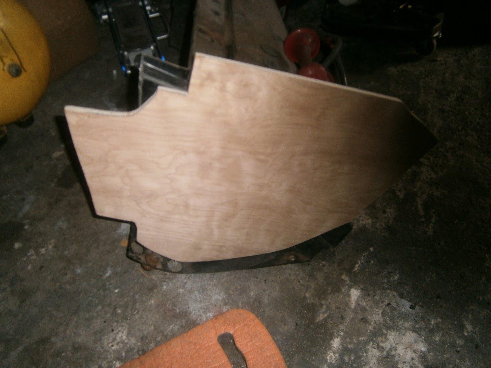
I taped the profile to the ply and cut it out using a jigsaw. The effect was OK and after sanding I got a pretty neat cut-out as below.
 |
| Plywood as cut out. The point fits into the front of the nose so the front of the car (forward) is to the right |

The ply fits nicely onto the sides of the fibre glass radiator box- which is promising- but there were three problems... I suspect that this could be because the template was generated for a later car and mine is one of the early ones.
Firstly, its clear from the pic above that the lower part at the front doesn't follow the curve of the radiator box (or of the car nose itself) - there is an unsightly gap (bottom right). This could be corrected by simply projecting the line of the front section downwards and that of the base forwards.
Secondly, the panel I removed didn't have this fancy curved section at the top left (pic reproduced below)
Instead it was simply a 6.5 inch straight cut (pic above). The curve might help fit a little on the left hand side, but its not needed on the right (and could be simplified for the left!).
Finally there is a cut-out at the lower left as above. I'm not sure why this is there but its clearly marked on the template and also present in at least one of the Lotus bits panels shown at the start of this blog. This cut-out obviously follows the line of the radiator box as above, and when the ply panel is inserted into the nose this cut-out exposes this 17mm nut at the rear of the headlamp pod housing void...
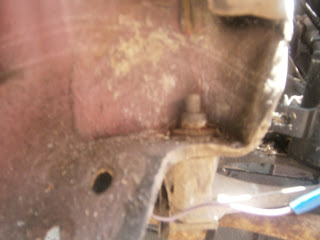
... This seems to be an attachment point between body and chassis but on further digging I find that its also used as an attachment point for the anti-roll bar: and if you need to remove/refit this then the bolt will simply turn unless you can hold this head. It can be done through the headlamp void but this is awkward so its possible the cut-out is reckoned to provide an easier access- although I think you would probably have to remove the radiator to use this route and to my mind removing the headlights would be easier... Its possible that this section was cut out simply because it
isn't covered by the radiator box sides and thus might be exposed to
too much weather and thus act as a focus for rot to form? I can't tell whether my originals had a cut-out in this position since both were rotten at the bottom and so this part was missing, but its really not like Lotus to think of providing access methods for jobs that might need to be done in the future or to think ahead for avoiding rot so my suspicion is that the cutout is just a bad fit in my car. As a compromise I fashioned a small insert panel that can be fixed onto the main panel to cover this gap and hopefully keep road muck out of the void.
I then cut out two further sections in which these modifications were made and used a combination of plane, surform and jig sawing to improve the profile-to-car match. If doing this job again I think its necessary to buy in some stiff artists' backing board (or similar) and refine the template to fit the individual car section before touching the wood.
The picture below shows the original profile and the modified profile I ended up with (including the detachable section). I will copy this onto paper and produce a more tailored "digitised" template to go with the first. I treated both panels to a good soaking in Cuprinol wood preservative paying special attention to the cut edges. I followed this with two coats of yacht varnish.
|
| Original profile |
 |
| LHS panel as modified- scalloped top simplified to rectangle, extra material at front bottom right and detachable flap fitting into recess at lower left. This may not be necessary- but Hey! Whilst I had the saw out.... |
I also "digitized" this panel profile and added it to the spreadsheet above. This is a larger profile and I would recommend cutting this one first as a trial fit- after all you can always make it smaller if you need to!
 |
| Larger profile as "digitised" If you are drawing my modified template then it should look like this when re-drawn. |
Fitting the panels:
This is the space into which the above panel should fit. The old panel was retained by fibreglass sheets in three positions:
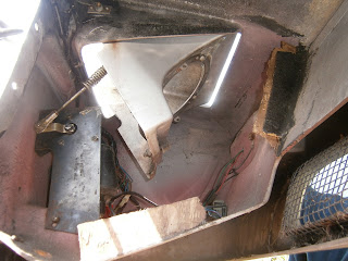 |
| Fibreglass matting fixings on lower and forward edges of the headlamp void, note inner leaf of the front mounting painted black |
At the front of the car (right in this pic) the sloping section was held between two folded fibreglass mats. As the wood has effectively disintegrated, these are now left standing with a handy wood-sized space between them. The sheet nearest the radiator is visible in this view painted black. Sadly its not possible to just slip the new panel into this groove because there is insufficient clearance.
At the base the wood was held against a single folded section of fibre glass matting visible in the photograph as an upstand.
At the rear the panel fits into a recess in the bulkhead. Additional matting sections held it in this groove
 |
| Bulkhead groove that retains the rear of the panel- its a loose fit! Remains of past fibreglass matting mount visible at the back of the groove. It would have been nicer to mould a slot of the right size into the body.... |
These matting mountings seem to be designed to hold the wood in place and prevent lateral movement, but they are not strong and would have little resistance in the case of sideways impacts. The strength of this arrangement is really only in the fore-and-aft direction. Head-on collision loads would compress the panel backwards into the moulded groove, transferring nose loads to the next bulkhead. The existing fibreglass can however be used to position the wood. In order to do this I had to cut off the black painted side of the fibreglass pair above.
 |
| Inner leaf of forward section removed exposing the outer sheet. |
I removed the innermost section matting from the forward pair (i.e. the black painted leaf). This exposed the back of the mounting and meant that I could test fit the panel by pushing it into place, back against the 2 remaining fibreglass leaves.
 |
| Test fitting of panel |
The panel as cut now fitted reasonably well although the profile at the top front could be better. Note the gap at the lower rear corner which could be filled if desired with the cut-out fillet. The panel couldn't fit back, flush with the lower edge of the nose because the fibreglass matting actually prevented it. In fact both left and right panels were oriented slightly inwards, converging towards the front of the car. I'm not sure if this is just careless fitting or to provide additional strength. I'd like to have fitted them flush with the body edge but the matting shows where it was originally fitted so I opted to refit the wood in the original position.
 |
| Right hand panel fitted in the same way, infill fillet could be positioned at lower right. I still need to drill this panel for the compressor mountings |
I will fit the panels using some new matting; but frankly I hate this method- its guaranteed to reduce my hands to sticky immobilised claws and I'm simply not gifted with fibre glassing. The old panel was fitted against some sort of caulking at the front to take up gaps, I surformed this off to get a smooth fit but I am expecting to need something similar and will try sticking the panel against the remaining up-stands of old matting using a modern waterproof adhesive (something like "No-more-nails" exterior formulation). This should also be able to replace any such caulking at the front. I will make a new leaf of matting to remake the inner leaf of the double cradle at the front of the panels and also to cover the existing upstands at the rear. Currently its my intention to use expanding builders' foam both to take up any gaps and secure the panel in the rear groove. This is pretty sticky stuff, dries to a hard, firm surface and being of closed cell structure, it is also waterproof. I like to think Lotus might have used this had it been around in '84.
I decided to dispense with my infill panels as I was now convinced that this space was always open. I amended the panels to the same profile in the lower corner and re-fitted the compressor mountings to the RHS before proceeding. Left hand panel stuck in place using waterproof adhesive ("No more nails extererior grade"). This was spread on the remaining fibreglass upstands and also along the edges of the nose and into the bulkhead recess. The panel was then pressed back into position and the adhesive smoothed over to fill any gaps. Remember to slip the compressor behind the Right hand panel before fitting and route out the wires through the top rear cut-out. Note the compressor mounting points restored before the panel was fitted.
 |
| Right hand panel first fit |
 |
| Left hand panel first fit. |
The glue was allowed to set overnight and then I fibreglassed in the missing section of the double upstand at the front of each panel. I used two layers of fibreglass matting with a reinforcing strip along the join.
 |
| Matting fibre-glassed in |
 |
| Matting fibre glassed in. |
The original sections of up-stand are now behind these panels. I want to apply more matting to cover these and bond to the panel, however this will have to be done through the headlamp opening- so fun and games there!
As predicted fibre glassing through the headlamp opening was challenging! I think if doing the job again I would definitely remove the pods- but in my case sorting the pods out was one of the jobs I did right back at the start of this project and I couldn't face undoing all that again! Anyway I did manage to get fibreglass matting on the backs of the panels, covering the up-stands remaining form the old wood and extending past them to stick onto the new.
I filled in around the rear of the wood (where it slips into the bulkhead) using builders foam.
 |
| Foam installed behind compressor |
I coated both the internal (i.e. radiator-facing) sides with a spray of black stone chip. This is another layer of protection and should make them less visible through the lower front nose grills.
The new wood is now in and I'm pleased I have a reconstituted nose section now. I think we are all impressed by the Elite winning the Don safety trophy.... but with duff panels I don't think it would have passed!