I tightened the motor mounting bolts from below. As the foot had been detached from the LHS mount, the top mounting stud was now inside the mounting leg but needed to be tightened. This could only be reached from underneath, from the other side of the car using a flat 17mm spanner. Once the motor was tight I could set about refitting the ancillaries, hoses and electrical wires.
I decided to start refitting things at the rear of the motor and work forwards so that hopefully this preserves access as I move forwards. The first thing I reattached was the crankcase to airbox breather pipe elbow. This has a jubliee clip at the crankcase end and a plastic clip at the airbox end. The clip is fastened by squeezing and unfastened by twisting.
 |
| Crankcase breather- will eventually connect to airbox. |
Next the heater hose (short hose) top pipe is attached to the head spigot- I applied corrosion block grease to help the seal and protect the spigot a little and then fastened it with a jubilee.
 |
| Engine to heater hose connection. |
The longer hose received the joining piece and second hose that will eventually connect to the water pump.
 |
| Heater pipe junction-heater to radiator |
Next I fitted the starter motor- there are three bolts to go here- two mount the motor itself and a third goes through the eye bolt. However the back of the solenoid sits very close to this structure and doesn't give enough space for a normal bolt head. Really it needs an M10 button-head Allen bolt but the only ones I had were too short. I reasoned that this is a relatively low stress area and so used an M8 Coach bolt which sits nicely in the hole and has a smooth rounded cap that dopes fit behind the solenoid. I used a nut M8 and M10 washers on the other end.
 |
| carriage bolt M8... M10 might be better? |
... as below.
 |
| carriage bolt head fits neatly. |
I could then fit the starter motor itself with the two bolts I removed when it was detached. These are fitted with their heads towards the clutch.
 |
| Starter fitted |
I added oil through the oil pressure take off point which should put some oil into the oil-way, before reattaching the oil pressure indicator feed.
 |
| Adding oil via the pressure indicator take-off point. |
Next I connected the high amperage leads to the starter- red from battery and brown to alternator. The end of the red lead was loosely bound in insulating tape so I covered this with some shrink tubing to give better protection.
 |
| solenoid connection |
and recovered the contact with the boot.
 |
| High amp leads on solenoid |
I reattached the red/white wire to the solenoid spade connector and installed the oil cooler take off plate (sandwich plate) with its new O ring which had been smeared with oil.
 |
| Sandwich plate fitted and swivelled into location on crankcase lug. |
Filled the oil filter with oil, smeared the sealing ring with more oil and then screwed it into place. Note the red/white wire now attached to solenoid.
 |
| Filter installed- filled with oil before mounting |
OK... OK I know- couldn't resist! It must be a car so I fitted the new gear knob!! Looks great...
 |
| New gear knob! Starting to look a little like a car! |
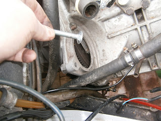
I next moved on to the oil cooler and associated pipework. I had intended to replace these pipes as they had been stressed during removal- however that was before I found out how much replacements cost! I decided to give the old ones a chance, but it was difficult to fit them for the same reason it had been hard to remove them! These two hoses have a rubber mid section into which are fitted metal end-pieces. These are angled through 90 degrees to mate with the fittings and carry the connectors for this purpose. These connectors should be free to rotate around the metal ends so that the pipes can be fitted in appropriate positions without strain as they are tightened. The pipe itself should be solid on the metal end pieces. I had already freed the termini at the sandwich plate end when I removed them, but the oil cooler ends were still locked fast. I was able to free them by gripping them in a vice and repeated wire brush cleaning, application of penetrating oil and twisting force! Eventually both ends worked free and I was able to remove much of the rust that had jammed them using spray penetrating oil; however its clear that both of my hoses do rotate on their metal ends but I am hoping that this won't translate into an oil leak.
 |
| Loosening the oil pipe termini |
I installed the oil cooler using 4 new M6 bolts, washers and spring washers- these were missing as the cooler was loose when I got the car. I needed to chase the threads of the weld nuts beneath the mounting bar. I filled the oil cooler with fresh oil and then attached the hoses to the cooler...
 |
| Oil cooler hose connections |
... and the sandwich plate and tightened all of them up'
 |
| Sandwich plate connections- note green and blue wire which will go to the temperature indicator in the water pump when that's fitted later. |
Moving to the lhs of the motor I fitted the PAS pump hoses. As the PAS pump was attached to the motor, I couldn't fit its hoses until the motor was in... this makes access a real pig! Here is the pump to rack hose which enters into the back of the pump. This type of connection always needs to be started by hand- like brake pipes and indeed the oil cooler pipes above, and finished with a spanner. However access is very poor. I managed to connect the fitting with fingers but tightening it proved very difficult. I eventually got to it using a 16mm crow's foot wrench on a 3/8 inch U/J and extension. A stubby spanner- or possibly a stubby brake-pipe spanner should also work.
 |
| Steering pump; pump-to-rack hose installed from the rear. The pump-to-reservoir mounting spigot is visible at the top. I have bought a new hose for this connection as I had to cut the original to detach it. |
 |
| pipe cut and fixed |
I fitted the new pump to reservoir hose which lacks metal termini using jubilee clips. The routing of this hose takes it close to the cam sprockets so its important to cut it to exact length and route it through the P clip. The belt guard will help keep this hose protected once its fitted.
 |
| New gasket for exhaust flange |
I also fitted the exhaust back onto the exhaust manifold flange including a new gasket. This is held on by 3 M8 studs and nuts. I used brass M8 nuts and had wanted to include washers under these, even though they are not shown in the parts diagram. However I discovered why these aren't fitted ... access is so bad that its not possible to fit them!
 |
Slip wobble bar extn between exhaust pipes to access central nut.
|
 |
| Fitted! |
Only one stud (rhs) can be reached readily. You cant get your fingers up to the other two so for these its best to offer up the nut to the stud inside a 13mm socket. I used a 1/4 drive socket on a long 1/4 inch wobble bar extension to thread the nut onto the lhs stud. For the centre stud you can poke the extension bar between the exhaust tubes and fit the 13mm socket onto the extn rod from the other side. It can then reach the centre stud easily between the tubes.
Moving to the front of the car I prepared to fit the radiator. I stuck the old foam strips to the top and bottom of the radiator using spray adhesive.
The radiator was then fixed to the top of the rad box and secured with its top nuts before adding the undertray. Despite my efforts to line everything up I found that the tray needed modification; largely because the repaired front mounting wings weren't just in the right position. Much of this mismatch was caused by my trying to fit the radiator upside down(!!), but sadly not all. Once it was turned the right way up fitting was easier!
 |
| Radiator fixed to top of box |
The radiator bottom tray does fit but the repairs I carried out to the mounting wings aren't quite right. Its fine for the time being but I think I will fit a new tray at some point in the future. In fact fitting the radiator turned out to be a bit of a trial. I refitted it three times (hint: its a good idea if the drain plug is at the bottom!) but eventually all the holes lined up perfectly and I could fit the rad.
 |
| Bottom tray fitted LHS , radiator mounting bolt (centre) and tray mounting bolts left of centre. |
 |
| Bottom tray RHS- radiator mounting bolt lower centre and tray mounting bolt centre right |
 |
| Radiator installed |
The fan mounts to the rad by 3x 10 mm M6 bolts screwing into weld nuts on the front of the radiator. The length is important as too long a bolt will damage the radiator. I test fitted it and the fan bracing strut using temporary bolts. Its clear that I will need to re-position the oil cooler pipes to avoid fouling the fan when I install properly.
 |
| Test fitting fan and brace strut- too close to oil cooler hoses. |
 |
| Drain hole in right orientation but too close to GRP bodywork for convenient access. |
Fitting the fan was more of a problem than I had expected. The stubby 10mm bolts are really fiddly and access is (as always) difficult. I investigated installing the fan on the LHS instead of the Right- this avoids any conflict with the oil cooler but I later discovered it blocks access to the lower radiator/pipe junction.
 |
| Tried fan on left? Obstructs pipework bottom left of radiator. |
I managed to rearrange the oil cooler hoses and move the radiator towards the nose to avoid conflict between the fan and cooler and then reinstall the fan on the RHS after all.
 |
| Rerouted oil cooler pipes and moved radiator more towards the nose at the bottom. The fan could then sit above them on the right |
The additional wires I found tied up in the nose have now been identified as the wiring for the second fan; obviously this is missing in my case so it seems the wires should have been tied up and hidden behind the radiator. The other connector is for the fan that I do have, but there is a problem with the fan connections. I don't understand why the fan needs this many wires- nor why the wires don't appear on the wiring diagram, but the fan is connected through a two plug connector and the wiring consists of a single green and black lead and 3 (!) all black leads. The black leads all appear to be earths and the G/B is the fan power supply- normally energised via the relay and controlled by otter switch. In my case the fan power lead (green/black) has been cut and attached to a spade connector. This would seem to be in an attempt to power the fan separately from the temperature controlled system- possibly manually, but no remnant of any such system survives.
 |
| Fan connections: There are three black leads (two that terminate in the two-pin connector, and a third that ends in a ring terminal) and a single green.black lead. This should connect back into the loom but in my case has clearly been cut and connected via a spade terminal to obrtain power elsewhere. |
I suspect all of this implies that the fan will not work as expected through the temperature control circuit. However I won't be able to tell what is wrong or to fix it unless I reconnect the leads so I have rejoined the broken wire and removed the spade connector. The black wire (ring terminal) has been attached to the motor body (this is a guess as the fan wasn't installed when I got the car) and the two pin connector plugged in the back of the fan. I will need to check all this before I power up in case the black wires are not all earths!
 |
| Green black wire reinstated. |
At this stage I turned my attention to the hoses.


No comments:
Post a Comment
Feel free to let me know what you think of this blog. I'm working on my own here so any feedback from those Lotus enthusiasts floating around "Blogger Bank" is welcome. Suggestions for process improvements especially welcome. If you like it please follow.