 |
| Car supported under chassis cross member. |
 |
| RHS (steering column side) rack mounting bolt visible to the rear of the rack next to the column entry |
 |
| LHS mounting bolt and gunge trap |
 |
| LHS rod end |
 |
| RHS rod end, note gaiter fragments |
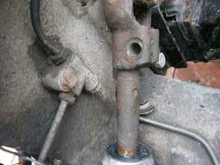
The final attachment is via the steering column UJ, that seems to be just one bolt. Note cap to rack column entry also broken!
 |
| Column bottom UJ which joins to the rack. |
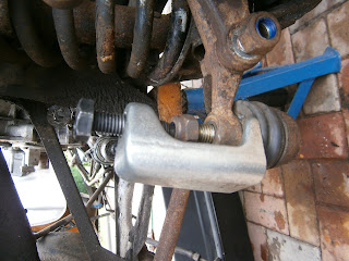
I could undo the ball joints easily- this canted ratchet handle is really useful here. A ball joint splitter made short work of the tapers.

The bolts enter from below and the nuts unscrew from the top- you may need to hold both ends which calls for very long arms. The bolts are fitted through two large stepped washers- I don't know why, but here you see the nut and upper washer, there is a large hole through the rack up the centre of which passes the bolt. You can tap that down (provided you haven't blocked it with your chassis beam!- I had and needed to reposition the wood cross beam slightly to allow the bolts to drop out.
 |
| Nut and stepped spacing washer -top of rack |
 |
| ... and the other side detached. Note gunge trap behind rack |
... and 17 mm spanner before..
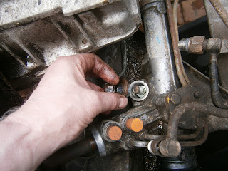
Blocking the holes with bungs. There seems to be the remnants of a "P" clip on the hose so I will need to investigate how these were fitted. I had to cut the single remaining P clip to release the hose.

 |
| Bolt out of UJ, but the rack wouldn't come out |
 |
| Column very stiff in UJ; rack cap has now given up entirely and fallen off. |
The UJ was very stiff on the splined shaft from the rack- it could be released by tapping GENTLY upwards while pulling the rack down.
Splines on the rack shaft very dirty, the UJ will also need a clean and probably a regrease, but I will check it for wear later.At this stage the rack was free and could be fineagled out of the car.
I hadn't removed the track rods as I thought it would be easier to do this whilst counting the turns unambiguously once the rack was out of the car.
I will add details of the refitting when I have got a renovated rack to fit! Frankly I was shocked by the state of the rack in the car and I'm not completely sure that its salvageable. I may be best to order a replacement "used" and have that reconditioned instead.
I took the rack to Steering Services in Dorking, great old fashioned engineering and I was pleased to find somewhere reasonably local. You can always tell you are in the presence of an expert when all the sizes get measured in imperial! The rack was identified as a Ford Sierra, possibly fitted with shorter arms. Anyway its been left for renovation- I will let you know how that goes.
I retrieved the rack from Steering Services. Looks very nice but it was a bit dearer than I had expected at £160 all in and didn't include new track rod ends. Not a big problem I thought as I had bought a new pair following advice from the forum... this suggested that the LDV Sherpa rod ends are the same as those on the Excel (QR1773 being the Quinton Hazel part no). I got a pair of these although they were designated as Vauxhall Victor FE. AT FIRST I thought these didn't fit... but that was a supplier error, the QR1773 is the right number!
When the rack was stripped I had a note of the amount of thread left exposed behind the track rod lock nuts. These were 5/8 and 7/16" Here the appropriate side is set to 5/8" before the track rod end was screwed up against the nut. I used copper anti-sieze as these will need adjusting later.
The wheel I knew was centralised, but I had to match this to the rack. I wound the rack to one extreme end and made marks on the steering column and rack. I could then wind the rack fully onto the opposite lock and count the turns. This gave a value of 3 1/4 turns. I turned back onto opposite lock to check count. From that position I could then turn back 1 5/8 turns to centralise the rack before fitting it to the car.
The rack is a little awkward to fiddle into place- I found if you insert the side away from the steering column first then you can just manage to get the steering column side in and slip in the UJ at the same time.
 |
| Splines started on UJ- tap on with hammer |
 |
| Rack in position and mountings aligned |
The bolts are awkward to fit as you need very long arms but by wedging a spanner on the topside you can get a torque wrench on the bolt underneath and fasten the bolts to the required torque (60 ft lb)
The track rod ends then fit into the steering arms and are tightened- you have to jam the tapers together to tighten the nut
 |
| Rack in position |
 |
| ... and this the smaller |
I removed the existing O rings by careful prying and replaced them with the new ones. Its important to lubricate the rings and the hose ends with steering fluid before assembling the rings onto the unions. Finally I screwed the two hoses into the holes that they had come from (now helpfully sealed with plastic plugs following the recon). These are a bit awkward as the threads are fiddly to mate whilst positioning the hose so as not to strain the joint, but do it by finger pressure alone, when they are right they will screw in easily. Use a wrench only for the final tightening. The low pressure (upper hose nearest the steering column) hose tightened down easily; but the high pressure hose left the pipe loose even when the nut was tight. The pipe could still be pulled to and fro in the union by about 2-3 mm. I doubt that this is right but haven't found an explanation yet.
Having re-stripped its clear that there is nothing preventing a good screw (!).
It seems that the sealing O ring washer is too small and can slip up inside the union itself thus removing compression on the joint. Perhaps the new one from Ford is too small or perhaps the union is worn on the inside? I am not yet sure if this is a problem with the sealing ring or the union.
The new o rings from Ford were 6mm id with 1.75mm cross-section. I think an R05 ring from my stock might be better. These are 6mm id but with a 2mm cross-section that might be enough to stop this slippage. I dont know if the material is compatible though so I soaked a ring in psf overnight to make sure it doesnt deteriorate in the fluid.
Note added Later- after the oil filter etc was refitted.... Refitting the steering hoses is a right royal pain in the bum! Its relatively easy if there is room and I fitted them at this stage without problems. Sadly I was forced to revisit the pas hoses once the oil cooler and the rest of the kit was installed. When the oil cooler is installed there really isn't enough room! I found the the pas hoses were running across the oil cooler and would obstruct airflow.
I did my best to sort this out but although the low pressure hose is quite defined in its route since it has to pass through the P clip which holds it to the rack, the same is not true of the high pressure hose and the two interfere. I spent a fruitless day loosening rerouting and refitting the hoses to try and get the best route. I failed. The best I can say is that its necessary to loosen the connection at the rear of the pump to get max swivel movement here which allows the hose to move across the car- this connection at the rear of the pump is very tricky to get at... I jacked up and supported the car, removed the wheel and then used a crowfoot spanner reaching awkwardly around the suspension arms. Its also really important to thread the rack unions with finger pressure alone as they are incredibly easily cross-threaded... if they thread at all that is. They will screw in easily but only if the angle is right in all dimensions. To find this sweet spot you really need the rest of the hose completely free to move. If finger pressure doesn't do it then the thread is probably wrong! Despite my best attempts the pressure hose still obstructs the oil cooler so I used some cable ties to hold the hose out of the way.
 |
| The pressure hose presses against the oil cooler. It seems to be that its bent too far outwards towards the cooler and could run closer against the rack. |
 |
| I removed the reservoir Low pressure hose to maximise freedom of movement in that hose |
 |
| Oil cooler refitted- despite all my attempts the hose still runs too closely against it. I used a cable tie to hold the hose away from the cooler and hopefully prevent any chafing. |


No comments:
Post a Comment
Feel free to let me know what you think of this blog. I'm working on my own here so any feedback from those Lotus enthusiasts floating around "Blogger Bank" is welcome. Suggestions for process improvements especially welcome. If you like it please follow.