I don't know anything much about the condition of this motor save that it looks OK so far! The crank seals look in good condition- no sign of leakage but changing them is one of those jobs best done when the motor is out so I'm going to tackle it. New seals are included in the top and bottom gasket sets from SJSportscars so what the hell.
Flywheel removal
The engine no for my car indicates that it was an automatic when new. However it does have a flywheel not a flexplate and there is a spigot bearing in the end of the crank. Maybe its been used a s a manual before but some early cars apparently had flywheels before the flexplate was introduced (to cure vibration I think) so I cant tell at the moment whether this applies to this car. The test would be so see if a manual clutch fits onto the pins in the crank but as I don't have one to test that I will have to wait. The fall back position is to put the flywheel from the car onto this motor, however what I have seen of the ring gear in the car suggests that this may need changing. On the other hand this one has terrible surface corrosion so would need resurfacing. I may be faced with fitting new ring gear to the car's flywheel or refacing this one- or both to one or the other- bummer! Lets try and keep the costs down and first step- remove the existing flywheel from the new motor.
Here dear reader, I confess an error- In order to undo the flywheel retaining bolts with a breakerbar and socket you need some decent clearance between the moveable struts of the engine stand mounting plate and the flywheel itself. I made the spacers to mount this engine (see earlier), and my concern at that time was not to put too much stress on them so I really wanted them short. I designed them to project just 1 inch from the Clarke's engine stand spigots and sadly this isn't enough, 2 inches is really minimum and for comfort maybe even 2.5 if you want to be able to remove the flywheel easily once its detached.
 |
| Home made spacer- really needs another inch clearance! |
 |
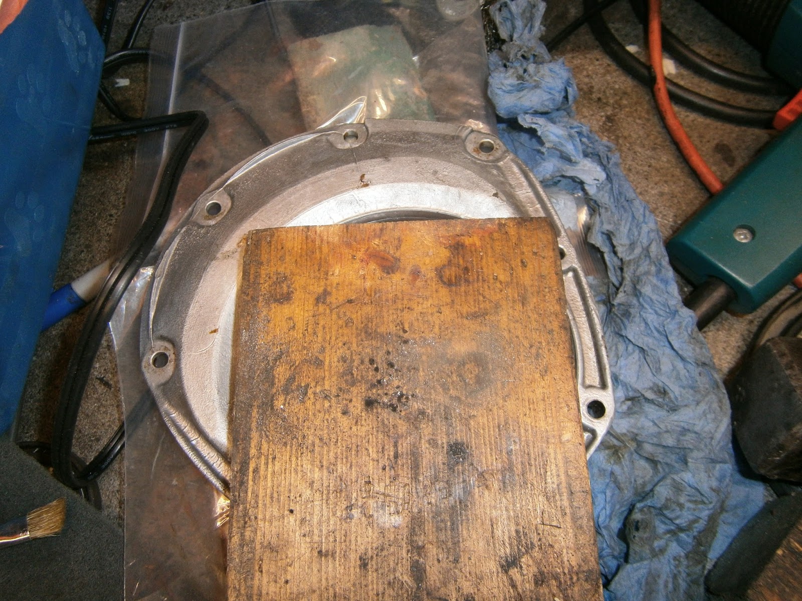
| Breaker bar inserted through stand stem, softwood block to prevent rotation |
Luckily I was able to reach the flywheel bolts down the hollow centre of the engine stand mounting. Its necessary to stop the flywheel turn while you undo the bolts and I did this with a piece of softwood between the ring gear and the engine stand attachment. The bolts came undone fairly easily, I noted that each of them has sealant in the threads since these bolts communicate with the crankcase interior and could potentially leak oil or crankcase gasses. As I want to reuse them I will need to chase these threads carefully to clean them out.
The flywheel was then only held on by an interference fit onto the crank journal. I have very little space between the stand and flywheel- impossible to fit a puller (even if I had one suitable). I therefore resorted to tapping the flywheel off using a wooden drift through the starter motor mounting hole and rotating the flywheel to even out any movement. Although I am sure this isn't the right way, the flywheel did at least came loose fairly easily. It could then only be removed after detaching one of the stand mounting arms (see poor clearance above). During this fiddly process I lost track of how it had been fitted onto the crank, but in fact it will fit onto the crankshaft mounting pins in only two orientations. Luckily both flywheel and crank journal have marks which must coincide to indicate the correct orientation. I am hoping the the flywheel and crank are balanced separately rather than as a unit since I may well need to swap flywheels!
 |
Note mark on flywheel which I think has to
correspond with a similar mark on
the crank journal
|
 |
| Alignment mark on Rear crank journal (extreme left) |
Rear Oil Seal Carrier
Having removed the flywheel, the oil seal carrier was revealed, this is held on by button screws across the top and bolts at the bottom. The button screws came undone using an Allen key and the bolts with a spanner. However according to the manual the special (thinner head bolts) should be fitted towards the bottom and screw into the main bearing panel.
 |
| Rear oil seal carrier, cap bolts loosened |
 |
| Oil slinger revealed beneath |
 |
| Nice clean seal carrier! |
Front Crankshaft oil seal
The front oils seal carrier is hidden behind the crank pulleys. I suspect that these are usually the devil of a job to shift but in my case they had obviously been taken off before, the drive belt pulley was missing and the cambelt pulley simply slid off.

 |
| Note drive belt pulley missing |
 |
| Nice clean front crank seal holder loosely replaced |
Refitting the Seals....!
The manual advises fitting the seals to the holders and then using a special tool to centre them as they are pushed over their shafts as the housing is fitted. Firstly a health warning- this section of my blog should not be read by genuine Lotus mechanics as it will horrify them... but I have fitted a large number of seals in the past and I've never needed to centre them. So... reasoning that as the housings are also free, the seals will adopt the most ergonomically favourable position during installation and that the bolts will automatically centre the housings (and thus the seals) anyway- I set about the task.
Since my motor is still on an engine stand, access to the rear seal is a little trying so I started with the front seal.
 |
| Front crank seal in place in housing, recessed from front... |
 |
| ...but flush at rear as recommended by the manual |
 |
| Wooden block in position |
 |
| ... and inverted ready to remove seal |
 |
| I used a draper oil and bearing set |
 |
| ... and the seal popped out easily |
 |
| New seal installed from the front using the seal driver as above, setting it flush with the rear of the casing as shown. |
 |
| Applied Wellseal around the crank at the front of the motor. |
 |
| ... and on the seal housing, before sticking the gasket to the motor (above) and offering up the housing. Note grease around oil seal lip and also around the shaft where the seal has to fit. |
 |
| Front seal housing reinstalled. |
Sadly the rear seal wasn't nearly as cooperative and although there seemed no need for any special tool for the front, maybe it would help at the back of the motor. This is my experience-I doubt if its the best way of doing this job.
However.. firstly I needed to check the seal position, there are several "score" marks on the rear crank where previous oil seals have worn grooves. The current seal had been positioned to miss these. Checking with a micrometer showed it was positioned app 2mm below the rear face of the housing, a little farther down than recommended for a clean shaft... it wasn't particularly straight either varying between just over 2 and nearly 4 mm!

 |
| To aid repositioning I drew a blue line around the seal recess just above the seal before I removed it. |
 |
| Supporting the housing between two blocks but leaving a narrow gap I was able to press the seal down with a punch and out of the front of the housing... Note: use the punch in the groove of the seal as shown, not around the edge where it might damage the alloy of the housing. |
 |
| Seal popped out with a few taps. No sign of Wellseal around it. |
 |
| Looks like someone hasn't been so careful in the past, bit of damage to seal housing. I smoothed this as much as I could before cleaning up the edges with carb cleaner. |
I put Wellseal around the housing edge and attempted to push the seal in using a combination of hand pressure (ineffective) and then a mallet using the old seal as a drift.- This was a disaster... The seal simply popped up the other side whenever it was tapped and Wellseal got on everything... rapidly reversing evolution and turning my hands to useless claws! I had no choice but to abandon the attempt and clean everything up- Wellseal does clean off well using paintbrush cleaner though!

 |
| I was able to tap it deeper with a loose board |

Finally I was able to tap the seal down to the right depth using the old seal as a drift, turning the housing over frequently and using the blue line to make sure it settled into the recess evenly. I managed to get it pretty much square at 2.3 mm depth from the rear face.
Fitting the rear housing was a big problem (experienced mechanics look away now!).
Since access was difficult owing to the engine stand I decided to add Wellseal to the housing mating surfaces (ie gasket surfaces), Fix the gasket to the housing and then add more sealant on top of the gasket. I then applied grease to the oil seal lip and the rear of the crankshaft. I had intended to then slip the housing up under the engine stand arms and press it forward onto the shaft, seating the seal as I went.... This is not actually possible as described because the oil seal will not slip over the shaft!!!
Mindful of the problems caused by sticky sealant I didn't want to start again so I held the cover in position with one bolt and fitted two top and bottom of the housing. This enabled me to tighten the housing down onto the shaft evenly. However, the seal lip will not slip over the shaft of its own accord! If you try it simply bulges outwards. I found it was necessary to pop it over the shaft with my fingers as soon as the bolts held it tight enough against the journal. I could then work my way around the seal just popping its lip over the shaft until I had got it all over. Then the housing could be pressed home with hand pressure and the bolts done up.
In order to do this I had used hex headed bolts at top and bottom as these are easier to turn but as it went home I had to shuffle these around again so that the Allen capped screws were at the bottom of the housing. This is the arrangement specified in the manual, but its not what I found when the housing was originally stripped.
 |
| Rear housing installed- seen from above, hex bolts installed... |
 |
| ... and below showing Allen button-capped screws in place |
I was then able to torque down all the bolts and screws evenly. Two pictures above show the seal in position. Will it leak??? Time will tell. This also reminds me that I need to change the spigot bearing in the end of the crank, although this will not be possible until the motor comes off the stand.
I don't know if the special tool would have helped in this case but my guess is that it probably would!
Last job today was to reinstall the oil gallery cover and seal the oil pressure take off with a rubber cap to stop any muck from dropping in.
 |
| Oil gallery cover re-installed. |
No comments:
Post a Comment
Feel free to let me know what you think of this blog. I'm working on my own here so any feedback from those Lotus enthusiasts floating around "Blogger Bank" is welcome. Suggestions for process improvements especially welcome. If you like it please follow.