Well- as work on the spare motor is drawing to a close and the bottom end just about done, its time, with some trepidation, to turn attention back to the car. So far I've been working in the garage and now I have to deal with all the access and positional problems inbuilt by Lotus!
Opinion is divided as to whether its best to remove the head with the engine in position or to remove the motor first. However there are 2 good reasons why I need to remove it in position:
Firstly, I don't actually know what's wrong with this motor apart from a severe and almost total loss of compression- perhaps it is fixable simply by a head overhaul and so perhaps the motor wont need to come out at all!... and secondly, I've sold my hoist with the intention of replacing it with a Sealey long-reach crane- which I don't yet have. Consequently removing the motor is out of the question at the moment... so time to tackle the head
in situ.... For this I'm following (roughly) the manual plus the guide from the lotus4seater forum
Luckily for me (?) since the car has been fiddled with for a while, it came to me with some of the initial parts removed already.
 |
| Bonnet held on by two Allen cap screws, 1 each side |
I removed the bonnet- beware this is really a two-person job as its unwieldy to get the second one out without scratching the bonnet, and then drained the radiator. The battery was already disconnected.
 |
| Radiator drain screw bottom left of radiator- hey! There really was some water left in this basket case! |
The air box/trunking and the cam belt guard were already off and in the boot! Consequently the first step was then to remove the intake manifold complete with carbs.
(NB... if I was doing this job again I would NOW say... The first job is to remove the Vee belts and then the Alternator and water pump. Its sort-of suggested in the manual that you can get away with leaving these in place, but in reality you cannot! You will find it impossible to release hoses from the manifold unless the water pump is off, and you cannot access the cam belt tensioner locking nut and adjustment screw until the alternator is off. These are dealt with below when I finally realised this, but be advised- do it now!)
 |
| Overview before starting |
 |
Choke synchronisation wire fixed nicely to forward
hand carb but... |
 |
| Mounting screw nut missing from rear carb. I replaced it temporarily with the body from a cable solderless nipple to hold everything in |
I disconnected the throttle cable from the rearmost carb and noted that the fixing screw lacked the rear pillar nut. I replaced this temporarily with the body from a solderless cable nipple.
|
| Choke cable detaches from inside the car- I opted to leave it in position and move the manifold over as there is plenty of spare length to allow me to move it. Note solderless nipple now installed on rear carb choke lever. Fuel pipes are lacking outer cover so I will need to source new ones. |
I left the choke cable in position and started removing the nuts, those across the top were easy, the two at either end were more difficult.
 |
| Fuel lines were undone- the car has been standing for years and there was no fuel to spill out. |
The forward nut is behind the thermostat and has a cross bonding connection. In order to remove this its necessary to remove the front (blocked) vacuum hose fixed to the manifold and the thermostat cover... it would probably have been simpler to remove the water pump entirely at this stage but I hadn't yet removed the V belts.
 |
| Front nut behind thermostat |
 |
| Remove the front vac take off spigot to access and remove the manifold nut, very nasty looking thermostat! |
 |
| Rear manifold nut is hidden beneath the rear vac take off (upper hose) for the brake servo and the HT leads and sandwiched behind the heater hose which attaches at the back of the inlet manifold |
 |
| Working from the other side of the car, Remove vacuum pipe to inlet manifold in order to access the rear nut which is seen here beside the heater take off hose. Note the second cross bonding strap here- currently disconnected- need to see where that should go for reassembly. |
Even after removing this pipe take-off, the nut was still awkward- finally got it with a 1/4 inch drive socket on a wobble extn bar. Turning attention back to the pump at the front of the block in order to remove the manifold I obviously needed to detach the hose from the manifold to the water pump
 |
| Hose between inlet manifold and water pump, note water temp gauge sender inserted into thermostat housing. |
This hose is virtually impossible to remove unless done at the same time as removing the pump- not at the same time as removing the manifold! I got it in the wrong order and had to cut the hose to remove it- definitely a better idea to remove the water pump before the inlet manifold. In fact this is obligatory on some cars before the head can come off anyway. I didn't think it applied to my model but I was wrong. Anyway this pipe was the last attachment and the inlet manifold could then be removed complete with the carbs. One observation is that this pipe looks like a plain straight length of pipe (as indeed it is shown on the parts list) and not the rather more expensive pipe with a slight bend sold as a replacement for this position- a straight one being listed only for the HC motor. Has the wrong one been used here? I am not sure which would be the best when rebuilding.
 |
| Inlet manifold removed. |
Before starting on the belts I put the motor in the timing position..
 |
| Crank timing mark aligned at TDC |
 |
| ... and at the same time the camwheels also aligned their timing marks and... |
 |
| This is a slightly later picture (Vee belts removed) but it shows the alignment of the ignition timing mark on the auxillary pulley (hard to see but at the bottom in pic above) with the centre line of that pulley and crank pulley when engine is in timing position. |
I have no idea what will eventually be refitted, but in case I do end up refitting this head I used the paint method to simplify timing restoration. Two paint marks are placed on teeth of the ignition and exhaust cam sprockets. These are positioned in areas where the belt makes good contact with each sprocket. I could then count the belt teeth between the White marks (24 teeth) in this case. If I refit this head then making sure I have the same number of teeth between these marks should preserve the timing, however its more likely I will end up refitting a different head and re-timing from first principles.
 |
| Timing paint marks added to ign (aux housing) and ex cam sprockets, 24 teeth on belt between the marks. |
I took some general views of how the vee belts were fitted...
 |
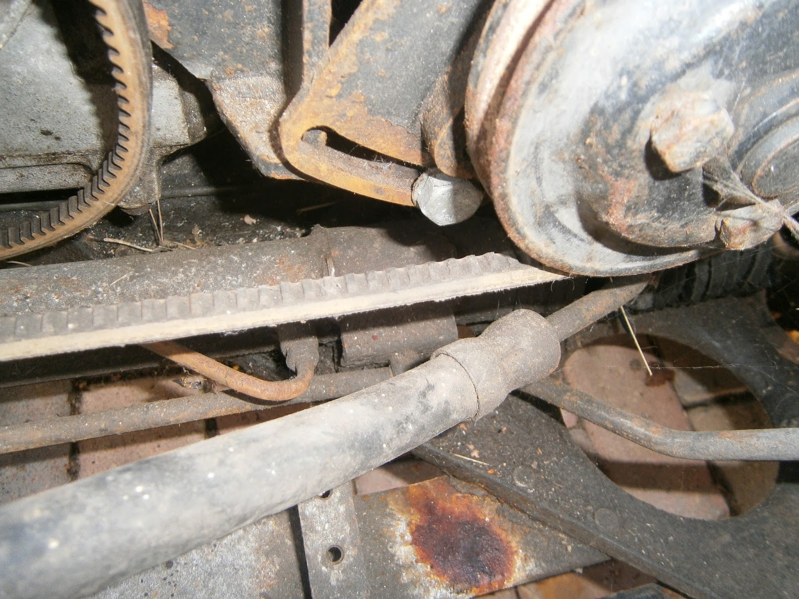
| Alternator drive belt, fitted to rear crank pulley groove and ... |
 |
| Vac pump belt fitted to front groove, water pump and vac pump |
Alternator was loosened and slipped inwards allowing the Alt drive belt to be removed from the pulleys although it cant come off until the vac pump belt is removed.
 |
| Lower alternator pivot bolt, loosen this and the top through bolt, push down to relieve belt tension. |
 |
| Vac pump pivot bolt- loosen with a hex key socket |
Vac pump loosened at the Allen bolt and slipped inwards to loosen the belt- it remained tighter than the alternator belt but could be removed.
 |
| Crank nut loosened |
Crank pulley bolt was removed by putting the car in gear and then using a breaker bar I could hit it with a mallet to shock the bolt loose against the engine and rear wheel movement. This also showed for the first time that I have a functioning clutch! The bolt came out surprisingly easily and then...
 |
| Crank pulley removed |
To my amazement the crank pulley simply pulled off with hand pressure alone! Of course this process moved the motor from the timing position so I will have to refit and return it to that point before removing the cam belt (see on). I then tried to remove the exhaust from the manifold. Access is very limited. There are three nuts holding the exhaust to the manifold. This was good news as the manifold that came with my spare motor was broken and only really supported 1 fastening properly. I jacked up the car but couldn't even see all of these bolts and had to proceed by touch. The first nut is fairly accessible and could be removed with a socket on an extension bar.
 |
| First bolt, nut has been (relatively) easily removed. Note engine mounting bracket above exhaust. |
 |
| Second nut wasn't visible inside the curve of the exhaust but I could feel it and eventually removed it using a stubby spanner |
Second nut was invisible! But I could remove it by "feel" using a stubby C spanner
 |
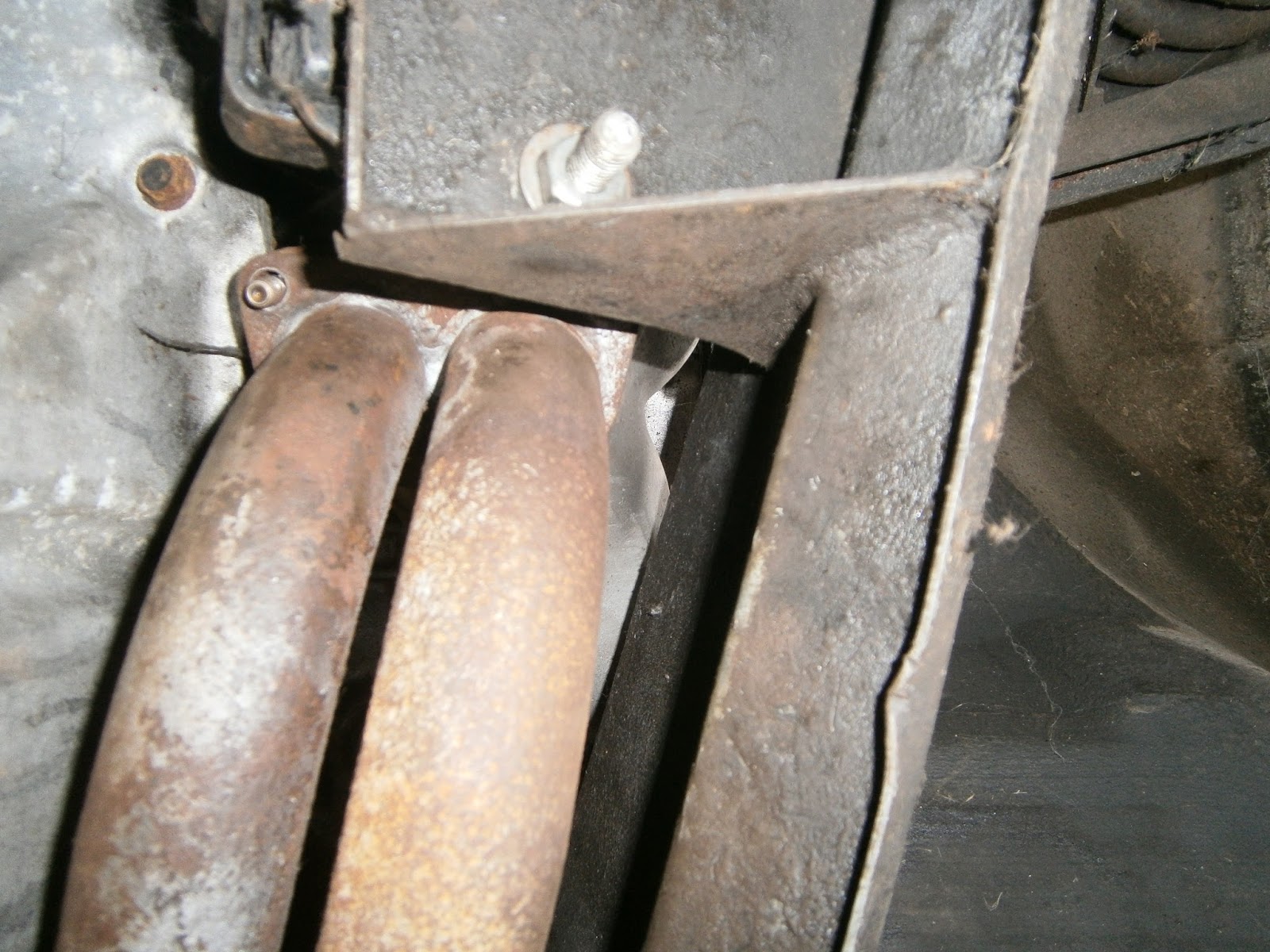
| Third nut hidden behind exhaust pipes and access is blocked by the engine mounting bracket. |
The third nut was undone (eventually) using a "C" or obstruction spanner fitted around the descending exhaust pipe. I could only get a few degrees of movement and a ratchet C spanner would have helped a lot. I had expected this step to be a nightmare but I suspect firstly that these nuts (brass) were installed with a lot of anti-seize copper grease, and secondly that they may have been fitted only loosely to prepare the car for sale after the LBPO discovered that the problem was more severe than he had hoped... call me paranoid but my experience has so far taught me to distrust most of what I was told....
Water pump
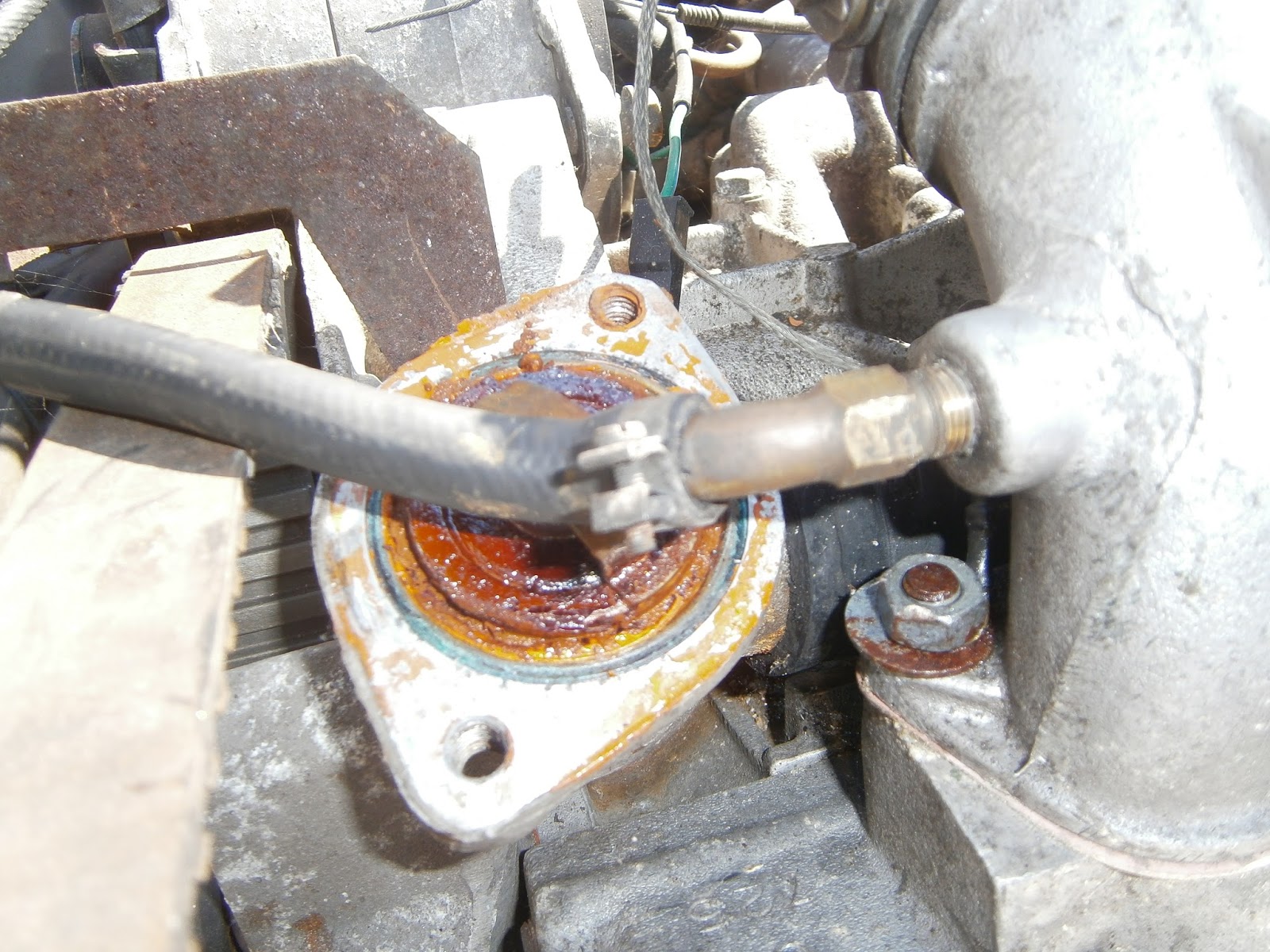
Belatedly (perhaps) I removed the water pump- 5 bolts, but in my case only 4 were fitted. There should be one behind the auxillary shaft pulley but that one was missing. Tim Engel points out that this bolt is often difficult to fit or remove because it can be fouled by the auxillary shaft pulley. This has obviously happened here and rather than deal with it the LBPO simply left the bolt out. Tim suggests replacing it with a hex head cap or button bolt which has a lower head and should be accessible through the pulley. This is the pre '86 pump (note the flat area in front of thermostat housing). The pump is held on by three small upper bolts and 2 larger ones which also fit the power steering pump bracket at the bottom of the pump.
 |
| heater return hose joining to front stub pipe, short junction pipe pump to aluminium elbow to right |
 |
| Hold one nut whilst undoing the next and work your way round. |
 |
| Pulley removed, hoses are next |
 |
| Hoses disconnected, heater pipe off, lower junction pipe detached. The inlet manifold to pump pipe was behind the pump in this view I simply cut it as it was stuck really firmly. Thermostat hose and housing was already removed. |
 |
| Pump removed |
Its fairly hard to get at some of these bolts and at least one looked like it will need rethreading as it was very worn. The pump sits behind the power steering pump bracket along its lower edge. This means you cant pull it forward to remove it, so break the seal by tapping downwards and then lift it up and out. This model of pump should have a gasket but was fitted with sealant alone.
Next step was to remove the tensioner and belt... however before this the tensioner needs to be slackened off. Unfortunately the tensioner adjuster is hidden behind the alternator so although I thought that I had got away with not removing it, it now had to come off.
 |
| Pictured before belt removal, The alternator(left) sits beside the tensioner(visible centre right with the cam belt going over its pulley). The alternator belt adjustment bracket is actually fitted using the tensioner-retaining bolts. In this position it blocks access to the tensioner adjustment screw and its locking nut. |
Alternator
Again this is the early type of fastening and lacks the triangular bracket, its a much simpler system. Its mounted by two bolts on the sliding bracket underneath and a single pivot bolt above. I undid these...
 |
| Alternator, lower bracket mounting bolts |
... and disconnected the wiring to the alternator.
 |
| Disconnect electrical cables |
There are 2 electrical connections to the alternator; a thick brown cable serving the starter motor which can be removed by folding back the rubber boot and unscrewing the nut. The smaller wire was at first a bit of a mystery, but it simply pulls off a ridged mounting stud.
 |
| Alternator upper bolt |
The upper bolt also attaches the belt cover mounting bracket. It has a washer and spring washer in front of- and a second washer behind- the forward mounting lug. The rear lug has a sleeve/spacer which can retain the alternator once the bolt has been removed. A little fiddling was needed to get the alternator out but it came fairly easily. As usual I refitted the bolt with its washers etc in order for safekeeping.
 |
| Alternator mounting bolt reinserted for safe keeping |
Tensioner
I put the motor back into the timing position and then turned it back to 90 deg btdc. This moves the pistons well down the bores and safely out of the way of anything embarrassing that might otherwise happen to them. Once the alternator was removed I could slacken the tensioner adjustment lock nut and then unscrew the adjuster- NB no more the 12 mm of thread in total should protrude from the tensioner body or the internal spring may fire the adjuster backwards at you.
 |
| Tensioner adjustment screw and locknut. |
The tensioner has to be retracted and locked before the cam belt can be removed or it will use its internal spring to self-destruct when the belt is taken off and fire its contents forward and all over the engine bay... good luck finding that lot! It can be locked with a 4 mm locking pin which will hold the teflon piston back against the spring... the idea being that you push the tensioner back into its body- simplest way is to press down on a run of the belt until the locking pin hole aligns with the groove in the teflon piston. However in my case... I couldn't find the locking pin hole! The tensioner cross bonding wire is broken off as well.. I need to find out where that would usually attach on the block.
Since I couldn't use the locking pin I pushed the tensioner bearing inwards against the spring to relieve belt tension, and held it there with a plastic ratchet tie.
 |
| Ratchet tie to hold tensioner wheel in the compressed position. |
I could then slide the cam belt off the pulleys; the tensioner bulged a little but remained intact. I then removed the through mounting bolt below the tensioner and the nut from the large stud to remove the tensioner itself. Note the spacers on long stud (1 at the rear, one at the front) and through bolt (1 at rear). The two rear spacers being of equal thickness, that in the front being thinner. This explained the difficulty in finding the locking pin hole as this turned out to be hidden behind the large stud nut and washer. Having removed the tensioner I was able to press the piston back a little further in the bench vice until the hole and groove coincided. I could then fit the locking pin properly. Here the tensioner is shown fitted loosely back in position with the pin protruding.
Cam covers and cam housings
It was now possible to get on with the job of removing the head itself... and hopefully solving the mystery of the non-existent compression in the cylinders. I removed the one remaining mounting bolt from the inlet cam cover- most were missing, cams looked better than I remembered, and then removed the exhaust cover which still had all but one of its bolts... although none of the SELOC washers.
 |
| Inlet cam cover removed |
 |
| Both cam covers removed, unscrewing the cam housing retaining bolts. |
Once the covers were off , it would be usual to determine the tappet clearances with a feeler gauge. However I am anticipating that all the valves will be at the very least reground, and some will very likely need to be replaced, or have new guides and their seats recut. In this case all the shim requirements would need to be redetermined anyway so I didn't bother to determine these clearances before removing the housings. The cam housing retaining bolts were undone- I used a deep 1/2 inch socket on all but a few and those that the deep socket wouldnt fit could be reached with a 1/4 inch drive socket. I was a bit concerned as these are meaty and torque-y nuts for such a small drive socket... but luckily the drive didn't break. Before I lifted the cam housings I placed small magnets on the tappet buckets beneath the cams to retain both tappet bucket and valve shim magnetically to the cams. I used the small magnets from a kit used to make plaster of Paris fridge magnets... my daughter got it for Christmas but only made one magnet! (See on).
 |
| All the valve shims lifted off with the cam housings, |
Well surprise no 1- I have all the valves! I had suspected that one or two might be missing completely. I stored the tappet buckets and shims in order in a head rack (nice bit of kit that) - just in case I refit any of these components.
 |
Magnet on top of tappet bucket...
|
 |
| ...and valve shim retained inside tappet bucket |
Cylinder head
Having removed the cam housings I could undo the head nuts in sequence as advised in the manual. These were still very tight- surprisingly as so many of the bolts I had encountered so far were either loosely tightened or absent! The rear water pipe connection has also to be removed from the head. However the head itself still couldn't be removed as there is insufficient clearance between the chassis members and the exhaust manifold. It may be possible to remove the head if (as the manual advises) you remove the exhaust manifold first; however as far as I can tell this is simply not feasible so its necessary to deal with the head/manifold combination.
There are two (related) methods for getting enough room to remove the head and both involve moving the engine.
The first requires that the left hand engine mounting be undone and the motor can then be jacked up, tilting it to the right to allow the head and manifold to clear the chassis.
The second is more drastic, the left hand mounting is undone as above but then the right hand is removed entirely. This isnt as bad as it sounds as access to this mounting is really good given the inclination of the motor. Of course you need to support the motor on a wheeled support or jack before you can do this. The whole motor can then be pushed to the right of the car on the wheeled jack to provide enough clearance. I decided to try the least complicated method first..
 |
| Viewed from under the car behind the front wheel, These are the two bolts securing the left engine mounting. One can be undone with a socket and extension but the other will need a ring spanner as the chassis blocks direct access. |
The engine mounting bolts were surprisingly loose and came off easily. The first time I tried jacking up the motor I left the nuts on loosely at the end of their bolts as I was worried the mounting wouldn't come down in the correct place to align the holes if it were not left with some connection to guide it back down. However this doesn't give enough room, its necessary to remove the nuts entirely and then jack up the motor, Luckily the engine does drop back into the same position (almost) although it needed a little persuasion to position the mounting with a lever. I lifted the motor using a low profile trolley jack (with a plank to spread the load) positioned under the left hand side of the sump.
 |
| Engine before jacking |
 |
| Jacked to right to provide extra room. |
At last I was able to remove the the cylinder head. It was however clear that the block hadn't drained fully (probably as the car is on a slight slope) and there was some escape of coolant as I raised the head. This flooded the cylinders and needed to be soaked up. I aspirated the rest out of the block using an old syringe.
Looking at the underside of the head, I had at least a partial answer to the lack of compression. Combustion chambers three and four had stuck exhaust valves- this motor has definitely thrown a cambelt at some time!
 |
| No 3 combustion chamber, jammed and bent exhaust valve |
 |
| No 4 combustion chamber. One valve also stuck in raised position, nasty deposition of some form of crud along the edge of the chamber. |
The bores were all very grubby and rusty at their tops. They have probably got wet, either by leakage in the head gasket, or since the car was left in the rain with no plugs in and an open bonnet. I cleaned them out with WD40 and a tissue but they still don't look great. I suspect that the rings might be rusty themselves and its pretty much impossible the clean down the side of the piston without removing them. I sprayed the bores liberally with WD40 and kept wiping it off and respraying. The jury is still out as to whether the block could be usable as it is. However, piston no 4 has also sustained some damage. There is a definite depression in its surface where its contacted the bent valve. I cant see any actual penetration but I suppose I cant rule out the possibility that the piston has been cracked, damaged or weakened. I don't really want to strip this motor as well as my spare, and anyway changing pistons will prove expensive as they should be changed as a matched set. I haven't fully decided but at the moment I think I favour swapping the motor for the recon unit I have produced. Luckily this motor does seem to have all the ancillaries needed to fit that although I will need to sort out a head to fit.
Well that finally reveals the LBPO for the liar he was. Throughout this strip I have found loose nuts, tricky bolts missing, peculiar threads wound around bolts to help them grip, gaskets missing or bodged- here is a piece of cardboard used to pack the exhaust manifold for heaven's sake!
I think its pretty obvious that this motor was stripped to find the problem, and then when it was identified as a large and expensive job the motor was simply put back together (with the cam belt in the right position) for sale. I don't think its possible that the LBPO could not have known the problems with this motor and his description at the time of sale was a pack of lies!


This is a great writeup, I'm staring down possibly having to dig in to my excel's engine and this gives me a good idea of what I'm signing myself up for. Thank you.
ReplyDelete